22 Installation Manual 3P291714-2B
DCM601A71 intelligent Touch Manager
English
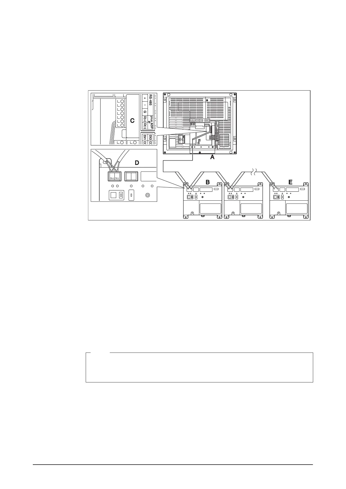
2.6.1 Terminal location and schematic connection diagram
Connect the iTM plus adaptor to the plus ADP IF terminal located on the rear face. Con-
nect the intelligent Touch Manager to the plus ADP IF terminal. As the terminals have
polarity, be sure to connect the positive wire to the “+” terminal and the negative wire to
the “–” terminal without fail. Connect the intelligent Touch Manager to the termination of
the RS-485 wiring.
<Terminal location and schematic connection diagram>
A intelligent Touch Manager
B iTM plus adaptor
C plus ADP IF (intelligent Touch Manager)
D plus ADP IF (iTM plus adaptor)
E iTM plus adaptor on which termination resistor must be enabled
(For details, refer to the “iTM plus adaptor installation manual” (EM11A030).)
2.6.2 Wiring specications
• Cable type: CPEV or FCPEV cable
• Core thickness: AWG 22-19
• Cable length: The overall cable length between the intelligent Touch Manager and the
terminal iTM plus adaptor is 164 ft. or less.
• Wiring connection type: Sequential connections
NOTE
Each air conditioner controlled via an iTM plus adaptor is also assigned a DIII address
between “1-00” to “4-15”. From the intelligent Touch Manager, it is recognized as “2:1-
00”, “3:1-02”, or the like, with the DIII-NET port number prexed.