30 Installation Manual 3P291714-2B
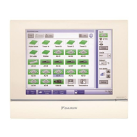
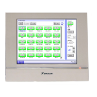
DCM601A71 intelligent Touch Manager
English
3.3 Mounting to control enclosure
3.3.1 Parts to be used
To mount the intelligent Touch Manager directly to the control enclosure, use the following
accessory mounting parts:
• Pan-head screw (M4×40, with spring washer and plain washer), 4 pcs.
• Nut (φ4), 4 pcs.
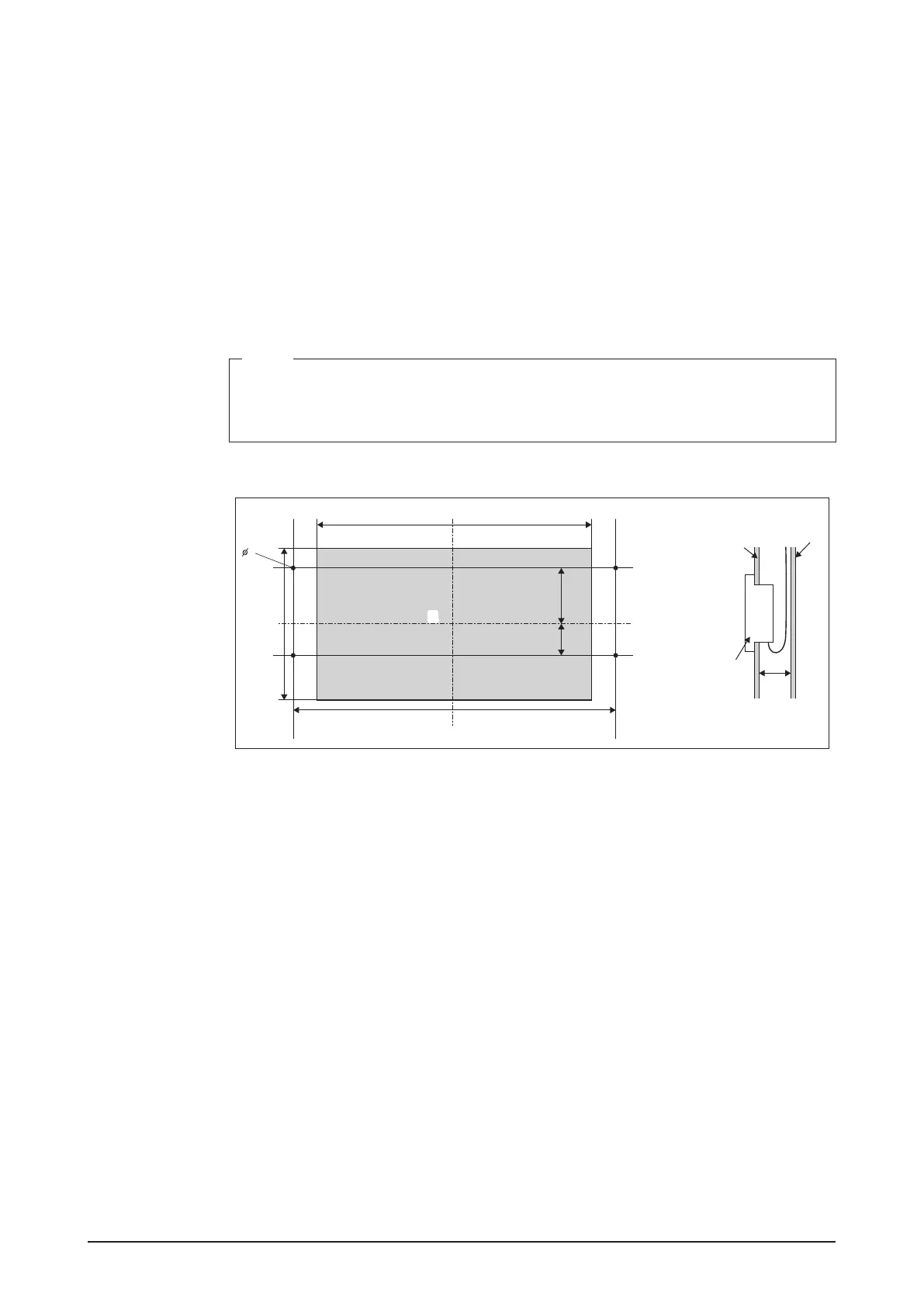
3.3.2 Wall opening dimensions
Use the following dimensional drawing to provide a sufcient opening.
NOTE
• The supplied paper template helps you mark the dimensions of the required wall
opening.
• Use the supplied paper template (Direct mounting to control enclosure).
<Wall opening dimensions for direct mounting to control enclosure>
10-1/8
8-5/32
10-23/32
2-3/8
3-5/8
4
(in.)
E
D
A
B
C
A Control enclosure face plate
B Control enclosure bottom board
C intelligent Touch Manager
D 31/32 in. min.
E Opening
3.3.3 Installation procedure
1. Remove the front panel of the intelligent Touch Manager, referring to Removing front
panel in section 3.2.3 Installation procedure.
This frame is snapped into the edge of the monitor display.
You can remove it by hand as it is not screwed.
After removing the front panel, the four holes (two holes on each right/left side) appears
around the monitor screen.
2. Insert the intelligent Touch Manager into the opening of the control enclosure and
install it to the control enclosure using the pan-head screws.
3. Attach the front panel of the intelligent Touch Manager back to its original position.