Installation Manual 3P291714-2B
DCM601A71 intelligent Touch Manager
19English
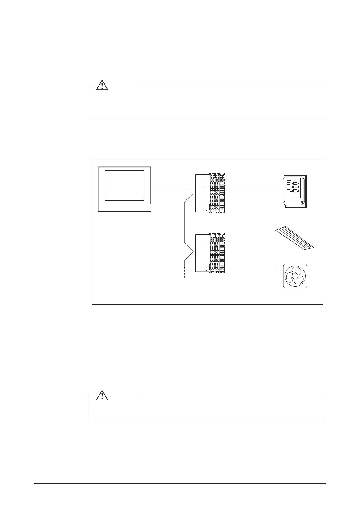
2.4 Connecting I/O module
In combination with the I/O module, the intelligent Touch Manager can monitor and control
a maximum of 960 contacts of non-DAIKIN peripheral devices such as lighting equipment
and security systems. Connect the intelligent Touch Manager to the termination of the
RS-485 wiring.
WARNING
• Be sure to perform the operation during power-off conditions. Not doing so
may cause an electric shock.
• Do not clamp the cables with high-current lines such as a power cable.
2.4.1 Terminal location and schematic connection diagram
<Schematic drawing of I/O module connection>
MONITOR
RS-485
The number of contacts per node
is up to 120. The maximum
number of nodes is 30.
Fan
Lighting
Wattmeter
Connect to the RS-485 terminals located on the rear face. As the terminals have polarity,
be sure to connect the positive core wire to the + (positive) terminal and the negative core
wire to the – (negative) terminal, respectively.
2.4.2 Wiring specications
• Cable type: CPEV or FCPEV cable (shielded type also acceptable)
• Cable length: 1640 ft. or less
• Core thickness: AWG 22-19
CAUTION
When using a shielded cable, be sure to connect the cable to the G (ground)
terminal.