18 Installation Manual 3P291714-2B
DCM601A71 intelligent Touch Manager
English
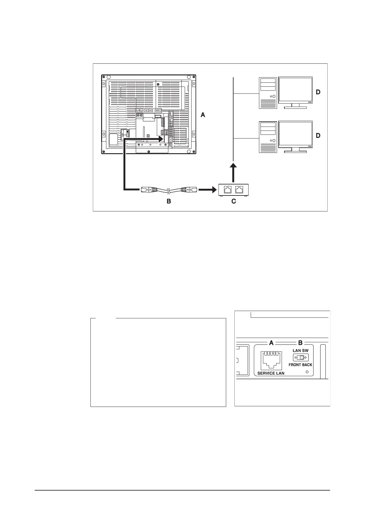
2.3.1 Terminal location and schematic connection diagram
Using a LAN cable, connect the LAN port to the network hub.
<LAN connection schematic diagram>
A Rear face of intelligent Touch Manager
B LAN cable
C Hub
D PC
2.3.2 Wiring specications
• Applicable cable standard: 100Base-TX or 10Base-T
• Connector standard: RJ-45
<SERVICE LAN socket and LAN SW
switch>
NOTE
• When you connect the intelligent Touch Man-
ager to the LAN temporarily during installation
or maintenance, use the SERVICE LAN port
located on the front face.
The SERVICE LAN port is enabled by chang-
ing the position of the LAN SW switch beside
the SERVICE LAN to the FRONT position.
• You cannot close the cover when the switch
set to “FRONT”. To close the cover, select
“BACK”.
A SERVICE LAN
B LAN SW