Installation Manual 3P291714-2B
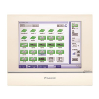
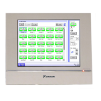
DCM601A71 intelligent Touch Manager
5English
Contents
1 Before Installation ................................................................................................... 7
1.1 Checking that all accessories are included ................................................................................ 7
1.2 Understanding external dimensions .......................................................................................... 8
1.3 Understanding where terminals and switches are located ...................................................... 10
1.3.1 Rear face ....................................................................................................................... 10
1.3.2 Front panel .................................................................................................................... 11
1.3.3 Side face ........................................................................................................................ 12
1.3.4 Wiring of cables ............................................................................................................. 12
1.4 Determining installation place .................................................................................................. 13
1.4.1 Installation place and mounting direction ...................................................................... 13
1.4.2 Environmental conditions .............................................................................................. 13
1.4.3 Required space ............................................................................................................. 13
2 Electric Wiring ........................................................................................................ 14
2.1 Removing wiring cover from rear face ..................................................................................... 14
2.2 Connecting DIII-NET-compatible air conditioning equipment ................................................... 14
2.2.1 Terminal location and schematic connection diagram ................................................... 15
2.2.2 Wiring specications ...................................................................................................... 16
2.2.3 Precautions for using multiple centralized controllers .................................................... 16
2.3 Connecting a LAN cable .......................................................................................................... 17
2.3.1 Terminal location and schematic connection diagram ................................................... 18
2.3.2 Wiring specications ...................................................................................................... 18
2.4 Connecting I/O module ............................................................................................................ 19
2.4.1 Terminal location and schematic connection diagram ................................................... 19
2.4.2 Wiring specications ...................................................................................................... 19
2.4.3 Address setup ................................................................................................................ 20
2.5 Connecting an emergency stop input device or power meter .................................................. 20
2.5.1 Terminal location and schematic connection diagram ................................................... 20
2.5.2 Wiring specications ...................................................................................................... 21
2.6 Connecting iTM plus adaptors ................................................................................................. 21
2.6.1 Terminal location and schematic connection diagram ................................................... 22
2.6.2 Wiring specications ...................................................................................................... 22
2.7 Connecting power supply ........................................................................................................ 23
2.7.1 Terminal location and schematic connection diagram ................................................... 23
2.7.2 Wiring specications ...................................................................................................... 24
3 Secure installation of intelligent Touch Manager ............................................... 25
3.1 Wall mounting .......................................................................................................................... 25
3.1.1 Parts to be used ............................................................................................................ 25
3.1.2 Installation procedure .................................................................................................... 26