Table 5 continued: Group 01: Operating Data
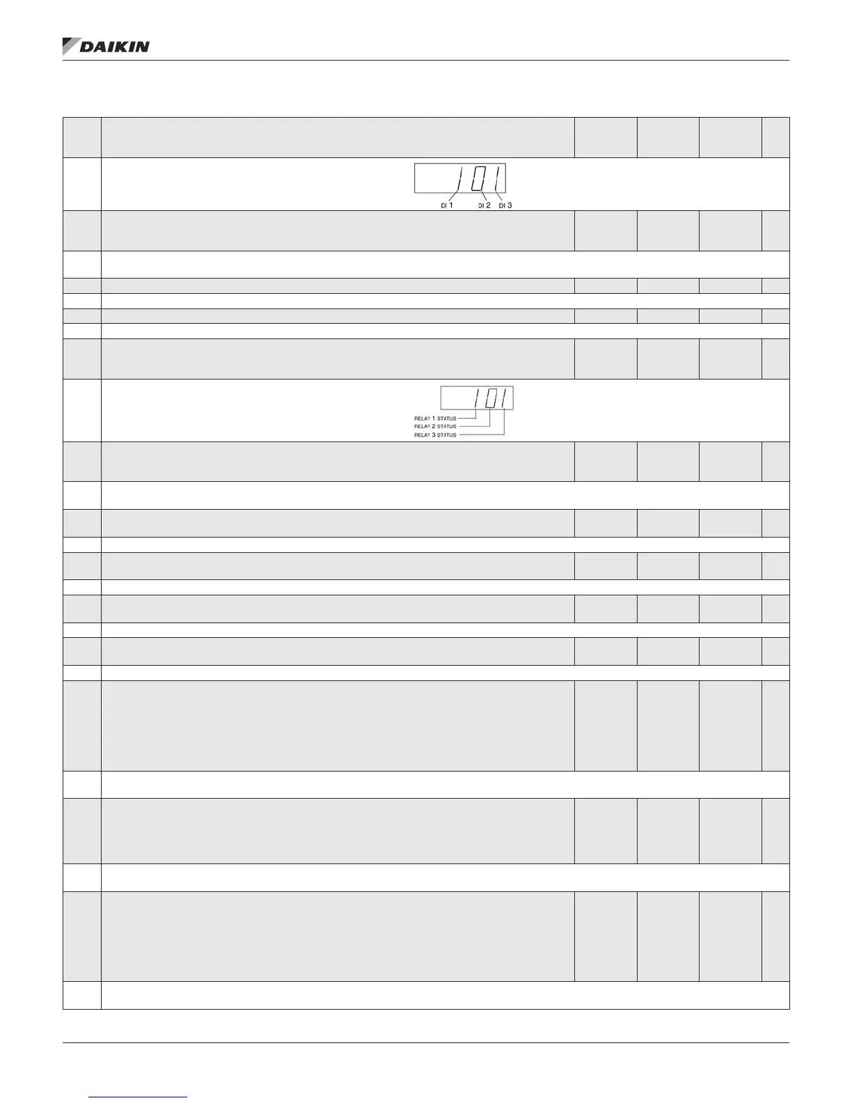
0118 DI 1-3 STATUS
000…111
(0…7
decimal)
1 —
Status of the three digital inputs.
• Status is displayed as a binary number.
• 1 indicates that the input is activated.
• 0 indicates that the input is deactivated.
0119 DI 4-6 STATUS
000…111
(0…7
decimal)
1 —
Status of the three digital inputs.
• See parameter 0118 DI 1-3 STATUS.
0120 AI 1 0.0…100.0% 0.1% —
The relative value of analog input 1 in %.
0121 AI 2 0.0…100.0% 0.1% —
The relative value of analog input 2 in %.
0122 RO 1-3 STATUS
000…111
(0…7
decimal)
1 —
Status of the three relay outputs.
• 1 indicates that the relay is energized.
• 0 indicates that the relay is de-energized.
0123 RO 4-6 STATUS
000…111
(0…7
decimal)
1 —
Status of the three relay outputs. Available if OREL-01 Relay Output Extension Module is installed.
• See parameter 0122.
0124 AO 1
0.0…20.0
mA
0.1 mA —
The analog output 1 value in milliamperes.
0125 AO 2
0.0…20.0
mA
0.1 mA —
The analog output 2 value in milliamperes.
0126 PID 1 OUTPUT
-1000.0…
1000.0%
0.1% —
The PID controller 1 output value in %.
0127 PID 2 OUTPUT
-100.0…
100.0%
0.1% —
The PID controller 2 output value in %.
0128 PID 1 SETPNT
Unit and
scale
dened
by par.
4006/4106
and
4007/4107
— —
The PID 1 controller setpoint signal.
• Units and scale dened by PID parameters.
0129 PID 2 SETPNT
Unit and
scale
dened by
par. 4206
and 4207
— —
The PID 2 controller setpoint signal.
• Units and scale dened by PID parameters.
0130 PID 1 FBK
Unit and
scale
dened
by par.
4006/4106
and
4007/4107
— —
The PID 1 controller feedback signal.
• Units and scale dened by PID parameters.
OM 1191 • MD5 VFD 14 www.DaikinApplied.com
ParaMeTers