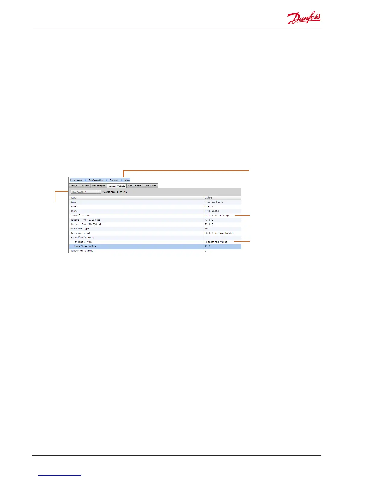
Variable Output Tab
Depending on control require-
ments the screen layout may
dier.
Example of Variable Output Tab
If congured,
navigate to
additional
Outputs via the
drop down box
Variable outputs
Using a 0-10V water mixing valve application as an example, the
following screen can be used on the AK-SM to provide control.
The same principles can be applied against a wide range of
control needs. Variable output control can also be seen in certain
AK-SM Refrigeration, HVAC and Lighting control screens. Using
the Miscellaneous area of the AK-SM a variable output point can
be created. After authorization, navigate to the conguration-
>control page. Enter the required quantity of variable outputs,
remembering to also add a sensor input (which will be later used
as a water temperature reference).
Next, navigate to the Misc tab and scroll to the variable output
tab. Enter a descriptive name and the board & point allocation
(the point number will be 1 to 4). Dene the working voltage
range, here a 0-10 V range is set. The previously congured sensor
Name: Enter custom description for Output
Bd-Pt: Enter a valid Board & Point address. Variable output is
done via VO2 board (described opposite)
Range: Select from various option in the drop down list:
0-10, 10-0, 0-5 Volts
Control Sensor
Output 0%
Output 100%
Override type (Relay Output, On/O)
Override point
Failsafe Type (Stay unchanged, Maximum output, Minimum
output, predened value - user denable)
Number of alarms: Enter the amount of alarms (max 3)
Alarm 1: Enter the alarm level (Disabled, Log only, Normal,
Severe, Critical)
Type: Alarm if above or if below limit (seen below)
Limit: Enter the alarm limit
Delay: Enter delay time
Units: Seconds, Minutes, Hours
From: Denes alarm output time window
To: Denes alarm output time window
Days: Dene the days associated with alarm
Action: Dene the alarm action
Controlling sensor
In this example the sensor was
pre-congured and labelled as
‘water temp’
Failsafe value (see below for
description)
input (water temp) can be dened, along with the output % range
and is used as the control reference point.
An override relay or switch can be added if required (not used
in this example). Finally an analog output fail safe can be
configured. The fail safe feature is to ensure safe operation during
power outages, network disturbances etc.
The following options are available;
• Stay unchanged - upon failure keep output voltage
unchanged
• Maximum output - set output to 100%
• Minimum output - set output to 0%
• Predefined value - user set value %
48 User Guide Lit. no. USCO.PI.R1.E1.02 © Danfoss 07-2013 AK-SM 850
 Loading...