Term.
no.
96 97 98 99
U V W
PE
1)
Motor voltage 0-100% of mains
voltage.
3 wires out of motor
U1 V1 W1
PE
1)
Delta-connected
W2 U2 V2 6 wires out of motor
U1 V1 W1
PE
1)
Star-connected U2, V2, W2
U2, V2 and W2 to be interconnected
separately.
Table 6.2 Terminal Descriptions
1)
Protected Earth Connection
U
1
V
1
W
1
175ZA114.11
96 97 98
96 97 98
FC
FC
Motor
Motor
U
2
V
2
W
2
U
1
V
1
W
1
U
2
V
2
W
2
Illustration 6.20 Star and Delta Connections
NOTICE
In motors without phase insulation paper or other
insulation reinforcement suitable for operation with
voltage supply (such as a frequency converter), fit a Sine-
wave filter on the output of the frequency converter.
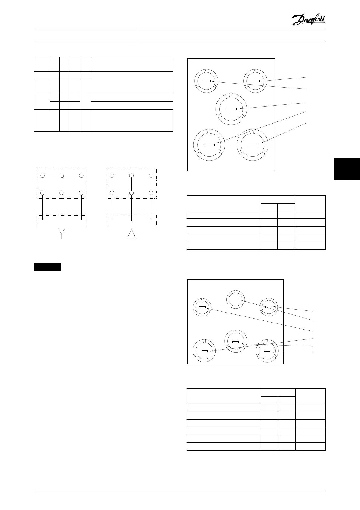
Cable entry holes
The suggested use of the holes are purely recommen-
dations and other solutions are possible. Unused cable
entry holes can be sealed with rubber grommets (for IP21).
* Tolerance ± 0.2 mm
[4]
[5]
[1]
[3]
[2]
130BB656.10
Illustration 6.21 A2 - IP21
Hole Number and recommended
use
Dimensions
1)
Nearest
metric
UL [in] [mm]
1) Mains 3/4 28.4 M25
2) Motor 3/4 28.4 M25
3) Brake/Load S 3/4 28.4 M25
4) Control Cable 1/2 22.5 M20
5) Control Cable 1/2 22.5 M20
Table 6.3 Legend to Illustration 6.21
1)
Tolerance
±
0.2 mm
[4]
[5]
[6]
[1]
[3]
[2]
130BB657.10
Illustration 6.22 A3 - IP21
Hole Number and recommended
use
Dimensions
1)
Nearest
metric
UL [in] [mm]
1) Mains 3/4 28.4 M25
2) Motor 3/4 28.4 M25
3) Brake/Load Sharing 3/4 28.4 M25
4) Control Cable 1/2 22.5 M20
5) Control Cable 1/2 22.5 M20
6) Control Cable 1/2 22.5 M20
Table 6.4 Legend to Illustration 6.22
1)
Tolerance
±
0.2 mm
Electrical Installation
Design Guide
MG11BC02 Danfoss A/S © Rev. 06/2014 All rights reserved. 89
6 6