[5]
[3]
[2]
[4]
[1]
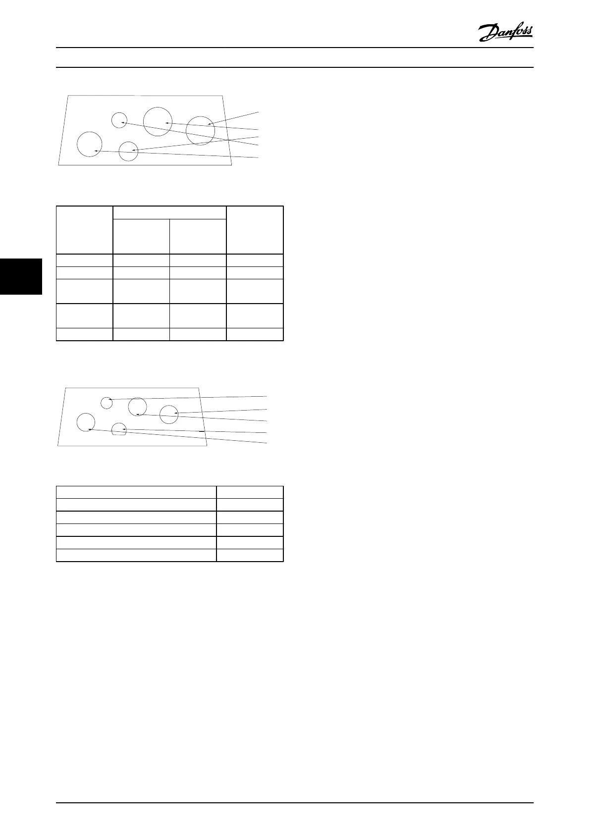
130BB663.10
Illustration 6.23 A4 - IP55
Hole Number
and
recommended
use
Dimensions
1)
Nearest metric
UL [in] [mm]
1) Mains 3/4 28.4 M25
2) Motor 3/4 28.4 M25
3) Brake/Load
Sharing
3/4 28.4 M25
4) Control
Cable
1/2 22.5 M20
5) Removed - - -
Table 6.5 Legend to Illustration 6.23
1)
Tolerance
±
0.2 mm
[4]
[2]
[3]
[5]
[1]
130BB665.10
Illustration 6.24 A4 - IP55 Threaded Gland Holes
Hole Number and recommended use Nearest metric
1) Mains M25
2) Motor M25
3) Brake/Load Sharing M25
4) Control Cable M16
5) Control Cable M20
Table 6.6 Legend to Illustration 6.24
Electrical Installation Design Guide
90 Danfoss A/S © Rev. 06/2014 All rights reserved. MG11BC02
66