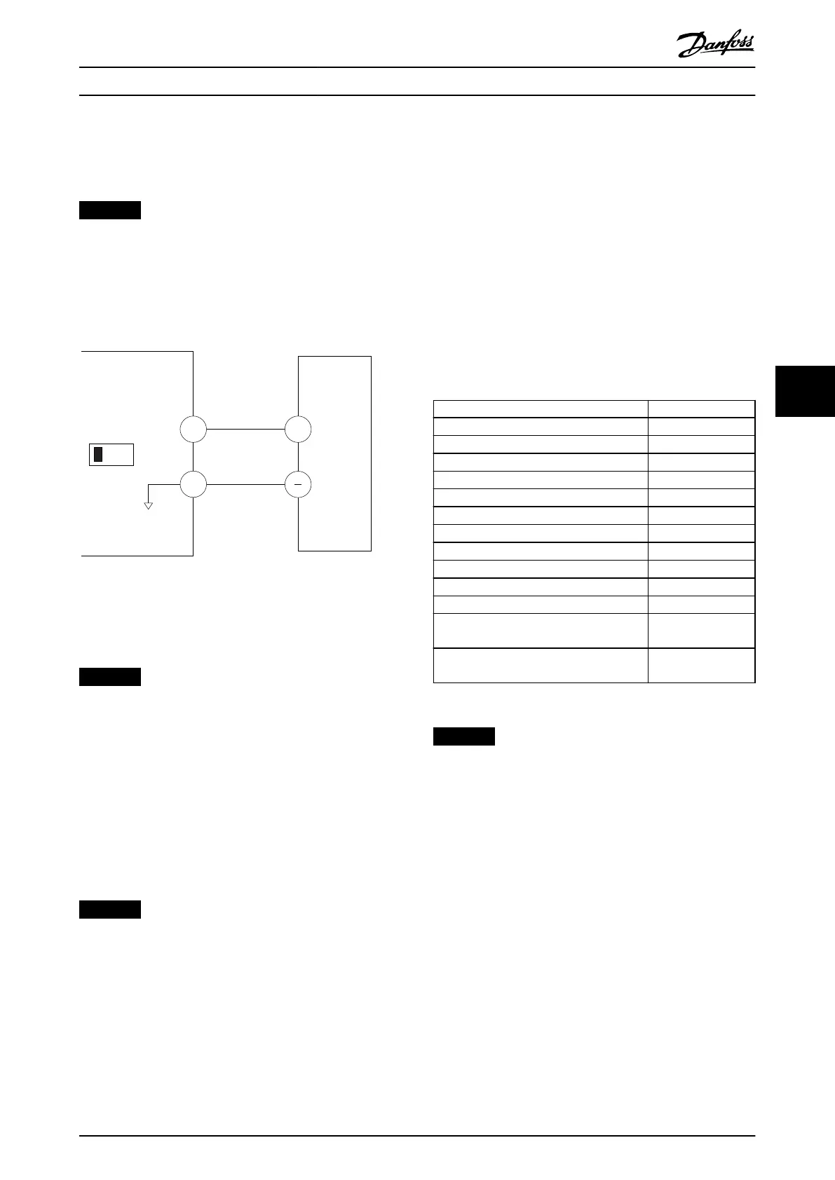
With an external device providing a 0–10 V control signal
connected to drive terminal 53, the system is now ready
for operation.
NOTICE
In Illustration 6.11, the scroll bar on the right of the
display is at the bottom. This position indicates the
procedure is complete.
Illustration 6.12 shows the wiring connections used to
enable the external device set up.
53
55
6-1*
+
A53
U - I
130BB482.10
0-10V
Illustration 6.12 Wiring Example for External Device Providing
0–10 V Control Signal
6.4.2 Entering System Information
NOTICE
SOFTWARE DOWNLOAD
For commissioning via PC, install MCT 10 Set-up
Software. The software is available for download (basic
version) or for ordering (advanced version, code number
130B1000). For more information and downloads, see
www.drives.danfoss.com/services/pc-tools.
The following steps are used to enter basic system
information into the drive. Recommended parameter
settings are intended for start-up and checkout purposes.
Application settings vary.
NOTICE
Although these steps assume that an asynchronous
motor is used, a permanent magnet motor can be used.
For more information on specic motor types, see the
product-specic programming guide.
1. Press [Main Menu] on the LCP.
2. Select 0-** Operation/Display and press [OK].
3. Select 0-0* Basic Settings and press [OK].
4. Select parameter 0-03 Regional Settings and
press [OK].
5. Select [0] International or [1] North America as
appropriate and press [OK]. (This action changes
the default settings for some basic parameters).
6. Press [Quick Menus] on the LCP and then select
02 Quick Setup.
7. Change the following parameters settings listed
in Table 6.3 if necessary. The motor data is found
on the motor nameplate.
Parameter Default setting
Parameter 0-01 Language English
Parameter 1-20 Motor Power [kW] 4.00 kW
Parameter 1-22 Motor Voltage 400 V
Parameter 1-23 Motor Frequency 50 Hz
Parameter 1-24 Motor Current 9.00 A
Parameter 1-25 Motor Nominal Speed 1420 RPM
Parameter 5-12 Terminal 27 Digital Input Coast inverse
Parameter 3-02 Minimum Reference 0.000 RPM
Parameter 3-03 Maximum Reference 1500.000 RPM
Parameter 3-41 Ramp 1 Ramp Up Time 3.00 s
Parameter 3-42 Ramp 1 Ramp Down Time 3.00 s
Parameter 3-13 Reference Site Linked to Hand/
Auto
Parameter 1-29 Automatic Motor Adaptation
(AMA)
O
Table 6.3 Quick Setup Settings
NOTICE
MISSING INPUT SIGNAL
When the LCP shows AUTO REMOTE COASTING or alarm
60, External Interlock, the unit is ready to operate but is
missing an input signal. See chapter 5.8.4 Enabling Motor
Operation (Terminal 27) for details.
Commissioning Operating Guide
MG16O102 Danfoss A/S © 01/2017 All rights reserved. 51
6
6