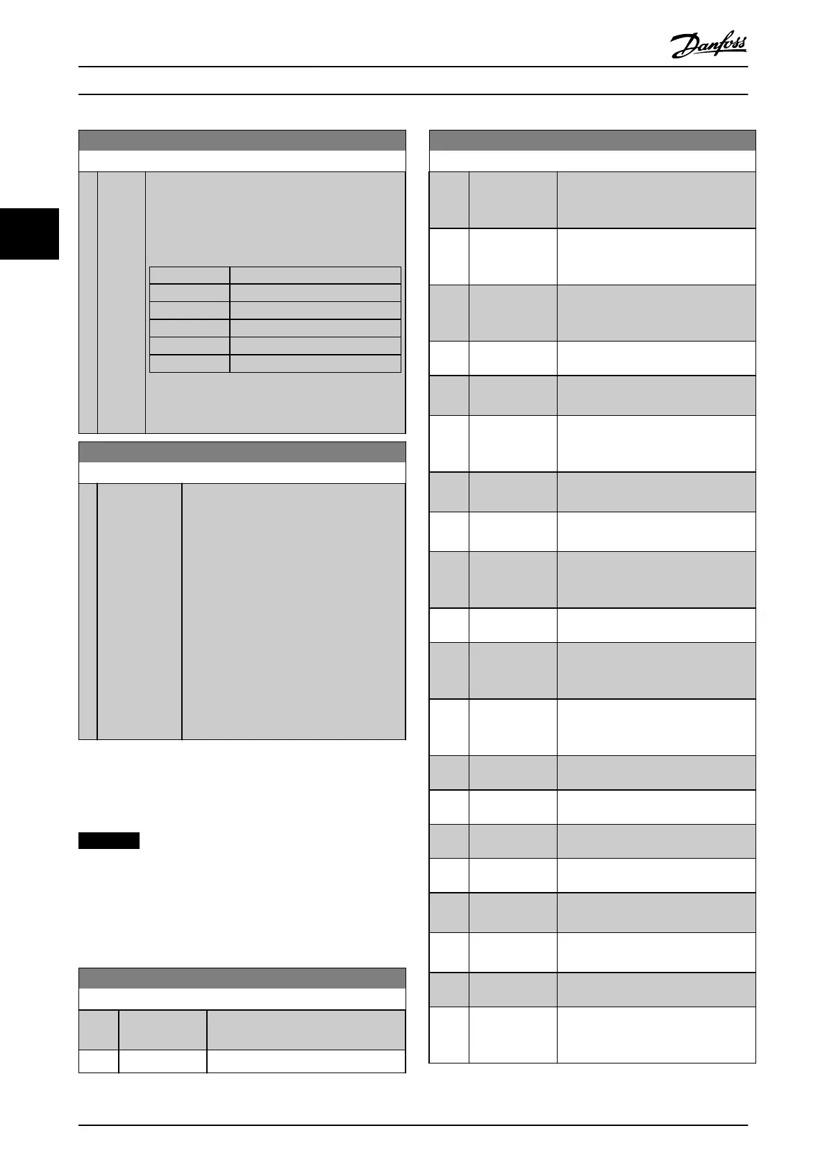
0-13 Readout: Linked Set-ups
Range: Function:
0* [0 -
255 ]
View a list of all the set-ups linked by means of
parameter 0-12 This Set-up Linked to. The parameter
has 1 index for each parameter set-up. The
parameter value displayed for each index represents
which set-ups are linked to that parameter set-up.
Index LCP value
0 {0}
1 {1,2}
2 {1,2}
3 {3}
4 {4}
Table 3.2 Example: Set-up 1 and Set-up 2 are
linked
0-14 Readout: Prog. Set-ups / Channel
Range: Function:
0* [-2147483648
- 2147483647 ]
View the setting of
parameter 0-11 Programming Set-up for each
of the 4 dierent communication channels.
When the number is displayed in hex, as it
is in the LCP, each number represents 1
channel.
Numbers 1-4 represent a set-up number; F
means factory setting, and A means active
set-up. The channels are, from right to left:
LCP, FC-bus, USB, HPFB1.5.
Example: The number AAAAAA21h means
that the FC-bus selected set-up 2 in
parameter 0-11 Programming Set-up, the LCP
selected set-up 1, and all others used the
active set-up.
3.2.3
0-2* LCP Display
Dene the variables displayed in the LCP.
NOTICE
For information on how to write display texts, refer to
•
Parameter 0-37 Display Text 1
•
Parameter 0-38 Display Text 2
•
Parameter 0-39 Display Text 3
0-20 Display Line 1.1 Small
Option: Function:
Select a variable for display in line 1,
left position.
[0] None No display value selected
0-20 Display Line 1.1 Small
Option: Function:
[37] Display Text 1 Enables an individual text string to be
written, for display in the LCP, or to be
read via serial communication.
[38] Display Text 2 Enables an individual text string to be
written, for display in the LCP, or to be
read via serial communication.
[39] Display Text 3 Enables an individual text string to be
written, for display in the LCP, or to be
read via serial communication.
[89] Date and Time
Readout
Displays the current date and time.
[953] Probus
Warning Word
Displays Probus communication
warnings.
[1005] Readout
Transmit Error
Counter
View the number of CAN control
transmission errors since the last
power-up.
[1006] Readout Receive
Error Counter
View the number of CAN control
receipt errors since the last power-up.
[1007] Readout Bus O
Counter
View the number of bus o-events
since the last power-up.
[1013] Warning
Parameter
View a DeviceNet-specic warning
word. 1 separate bit is assigned to
every warning.
[1115] LON Warning
Word
Shows the LON-specic warnings.
[1117] XIF Revision Shows the version of the external
interface le of the Neuron C chip on
the LON option.
[1118] LonWorks
Revision
Shows the software version of the
application program of the Neuron C
chip on the LON option.
[1230] Warning
Parameter
[1397] Alert Alarm
Word
[1398] Alert Warning
Word
[1399] Alert Status
Word
[1501] Running Hours View the number of running hours of
the motor.
[1502] kWh Counter View the mains power consumption in
kWh.
[1580] Fan Running
Hours
[1600] Control Word View the control word sent from the
frequency converter via the serial
communication port in hex code.
Parameter Descriptions
VLT
®
HVAC Drive FC 102
28 Danfoss A/S © 03/2015 All rights reserved. MG11CE02
33
 Loading...


