0-11 Programming Set-up
Option: Function:
Select the set-up to be edited (that is
programmed) during operation; either the
active set-up or 1 of the inactive set-ups. The
set-up number being edited is displayed in the
LCP in brackets.
[0] Factory
setup
Cannot be edited, but it is useful as a data
source to return the other set-ups to a known
state.
[1] Set-up 1
[1] Set-up 1 to [4] Set-up 4 can be edited freely
during operation, independently of the active
set-up.
[2] Set-up 2
[3] Set-up 3
[4] Set-up 4
[9] * Active Set-
up
(I.e. the set-up in which the frequency
converter is operating) can also be edited
during operation. Editing parameters in the
selected set-up would normally be done from
the LCP, but it is also possible from any of the
serial communication ports.
0-12 This Set-up Linked to
Option: Function:
This parameter only needs to be programmed if
changing set-ups is required while the motor is
running. It ensures that parameters which are
‘not changeable during operation’ have the same
setting in all relevant set-ups.
To enable conict-free changes from 1 set-up to
another while the frequency converter is
running, link set-ups containing parameters
which are not changeable during operation.
The link ensures synchronising of the not
changeable during operation parameter values
when moving from 1 set-up to another during
operation. Not changeable during operation
parameters can be
identied by the label FALSE
in the parameter lists in chapter 5 Parameter
Lists.
The parameter 0-12 This Set-up Linked to feature
is used when [9] Multi set-up in
parameter 0-10 Active Set-up is selected. [9] Multi
set-up can be used to move from 1 set-up to
another during operation while the motor runs.
xample:
Use [9] Multi set-up to shift from set-up 1 to set-
up 2 while the motor runs. Programme
parameters in set-up 1
rst, then ensure that
set-up 1 and set-up 2 are synchronised (or
linked). Synchronisation can be performed in 2
ways:
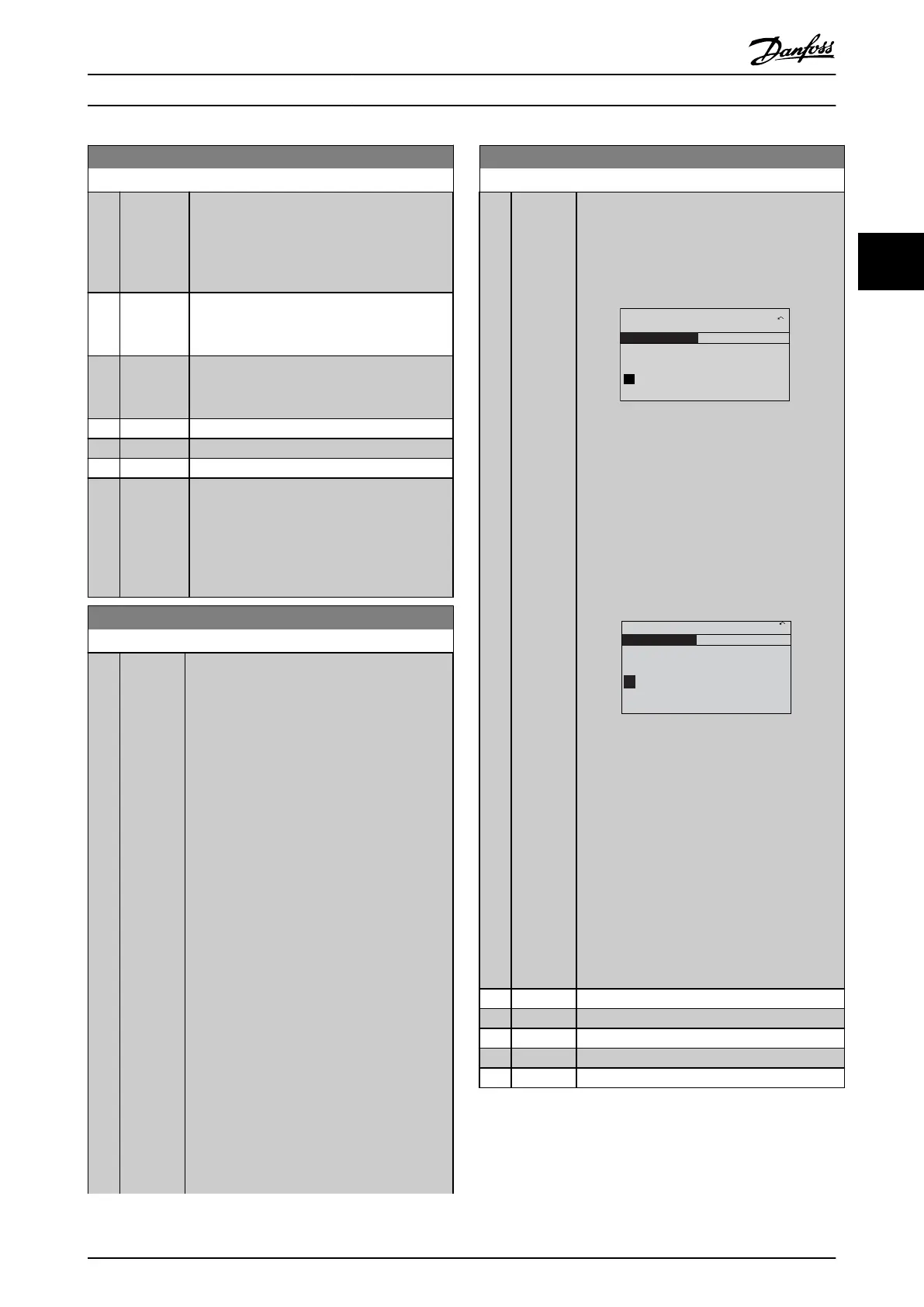
0-12 This Set-up Linked to
Option: Function:
•
Change the edit set-up to [2] Set-up 2
in parameter 0-11 Programming Set-up
and set parameter 0-12 This Set-up
Linked to to [1] Set-up 1. This starts the
linking (synchronising) process.
130BP075.10
0-12 This Set-up Linked to
0 RPM
0.00A
1(1)
Set-up Handling 0-1*
[1]
Setup 1
Illustration 3.1 Set-up Handling
OR
•
While still in set-up 1, using
parameter 0-50 LCP Copy, copy set-up
1 to set-up 2. Then set
parameter 0-12 This Set-up Linked to to
[2] Set-up 2. This starts the linking
process.
130BP076.10
0-12 This Set-up Linked to
0 RPM
0.00A
1(1)
Set-up Handling
0-1*
[2]
Setup 2
Illustration 3.2 Set-up Handling
After the link is complete,
parameter 0-13 Readout: Linked Set-ups reads
set-ups 1 and 2 to indicate that all not
changeable during operation parameters are now
the same in set-up 1 and set-up 2. If there are
changes to a not changeable during operation
parameter, for example parameter 1-30 Stator
Resistance (Rs), in set-up 2, they are also
changed automatically in set-up 1. A switch
between set-up 1 and set-up 2 during
operation is now possible.
[0]
* Not linked
[1] Set-up 1
[2] Set-up 2
[3] Set-up 3
[4] Set-up 4
Parameter Descriptions Programming Guide
MG11CE02 Danfoss A/S © 03/2015 All rights reserved. 27
3 3
 Loading...


