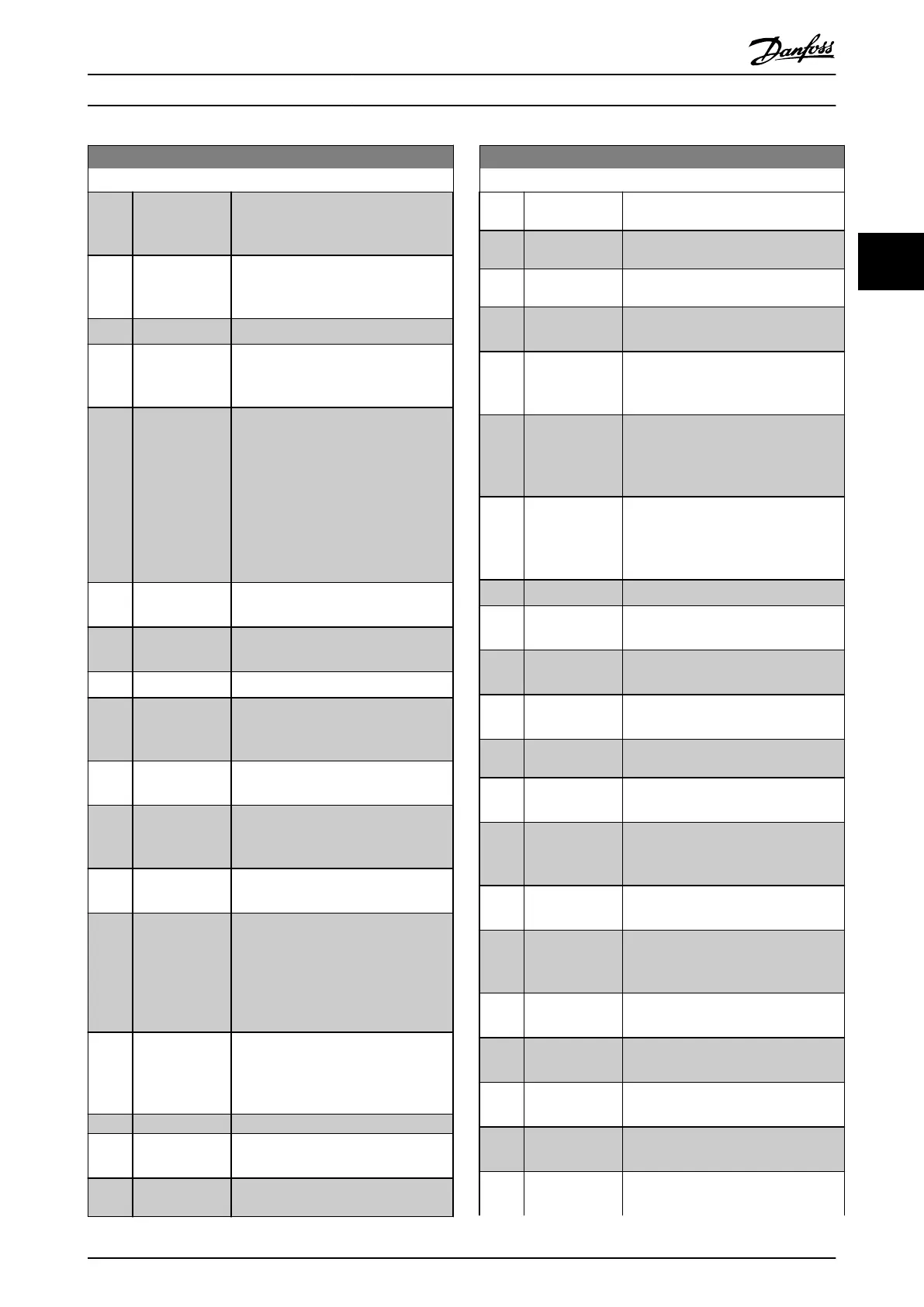
0-20 Display Line 1.1 Small
Option: Function:
[1601] Reference [Unit] Total reference (sum of digital/analog/
preset/bus/freeze ref./catch up and
slow-down) in selected unit.
[1602]
*
Reference [%] Total reference (sum of digital/analog/
preset/bus/freeze ref./catch up and
slow-down) in percent.
[1603] Status Word Present status word
[1605] Main Actual
Value [%]
View the 2-byte word sent with the
status word to the bus master
reporting the main actual value.
[1609] Custom Readout View the user-dened readouts as
dened in
•
Parameter 0-30 Custom
Readout Unit,
•
Parameter 0-31 Custom
Readout Min Value,
•
Parameter 0-32 Custom
Readout Max Value.
[1610] Power [kW] Actual power consumed by the motor
in kW.
[1611] Power [hp] Actual power consumed by the motor
in hp.
[1612] Motor Voltage Voltage supplied to the motor.
[1613] Frequency Motor frequency, that is the output
frequency from the frequency
converter in Hz.
[1614] Motor current Phase current of the motor measured
as eective value.
[1615] Frequency [%] Motor frequency, that is the output
frequency from the frequency
converter in percent.
[1616] Torque [Nm] Present motor load as a percentage of
the rated motor torque.
[1617] Speed [RPM] Motor speed reference. Actual speed-
depends on slip compensation being
used (compensation set in
parameter 1-62 Slip Compensation). If
not used, actual speed is the value
read in the display minus motor slip.
[1618] Motor Thermal Thermal load on the motor, calculated
by the ETR function. See also
parameter group 1-9* Motor
Temperature.
[1620] Motor Angle
[1622] Torque [%] Shows the actual torque produced, in
percentage.
[1623] Motor Shaft
Power [kW]
0-20 Display Line 1.1 Small
Option: Function:
[1624] Calibrated Stator
Resistance
[1626] Power Filtered
[kW]
[1627] Power Filtered
[hp]
[1630] DC Link Voltage Intermediate circuit voltage in the
frequency converter.
[1632] Brake Energy /s Present brake power transferred to an
external brake resistor.
Stated as an instantaneous value.
[1633] Brake Energy
Average
Brake power transferred to an external
brake resistor. The mean power is
calculated continuously for the most
recent 120 s.
[1634] Heatsink Temp. Present heat sink temperature of the
frequency converter. The cut-out limit
is 95 ±5 °C; cutting back in occurs at
70 ± 5 °C.
[1635] Inverter Thermal Percentage load of the inverters.
[1636] Inv. Nom.
Current
Nominal current of the frequency
converter.
[1637] Inv. Max.
Current
Maximum current of the frequency
converter.
[1638] SL Controller
State
State of the event executed by the
control.
[1639] Control Card
Temp.
Temperature of the control card.
[1643] Timed Actions
Status
See parameter group 23-0* Timed
Actions.
[1650] External
Reference
Sum of the external reference as a
percentage, that is the sum of analog/
pulse/bus.
[1652] Feedback[Unit] Reference value from programmed
digital input(s).
[1653] Digi Pot
Reference
View the contribution of the digital
potentiometer to the actual reference
feedback.
[1654] Feedback 1
[Unit]
View the value of feedback 1. See also
parameter group 20-0* FC Closed Loop.
[1655] Feedback 2
[Unit]
View the value of feedback 2. See also
parameter group 20-0* FC Closed Loop.
[1656] Feedback 3
[Unit]
View the value of feedback 3. See also
parameter group 20-0* FC Closed Loop.
[1658] PID Output [%] Returns the drive closed loop PID
controller output value in percent.
[1660] Digital Input Displays the status of the digital inputs.
Signal low=0; Signal high=1.
Parameter Descriptions Programming Guide
MG11CE02 Danfoss A/S © 03/2015 All rights reserved. 29
3 3
 Loading...


