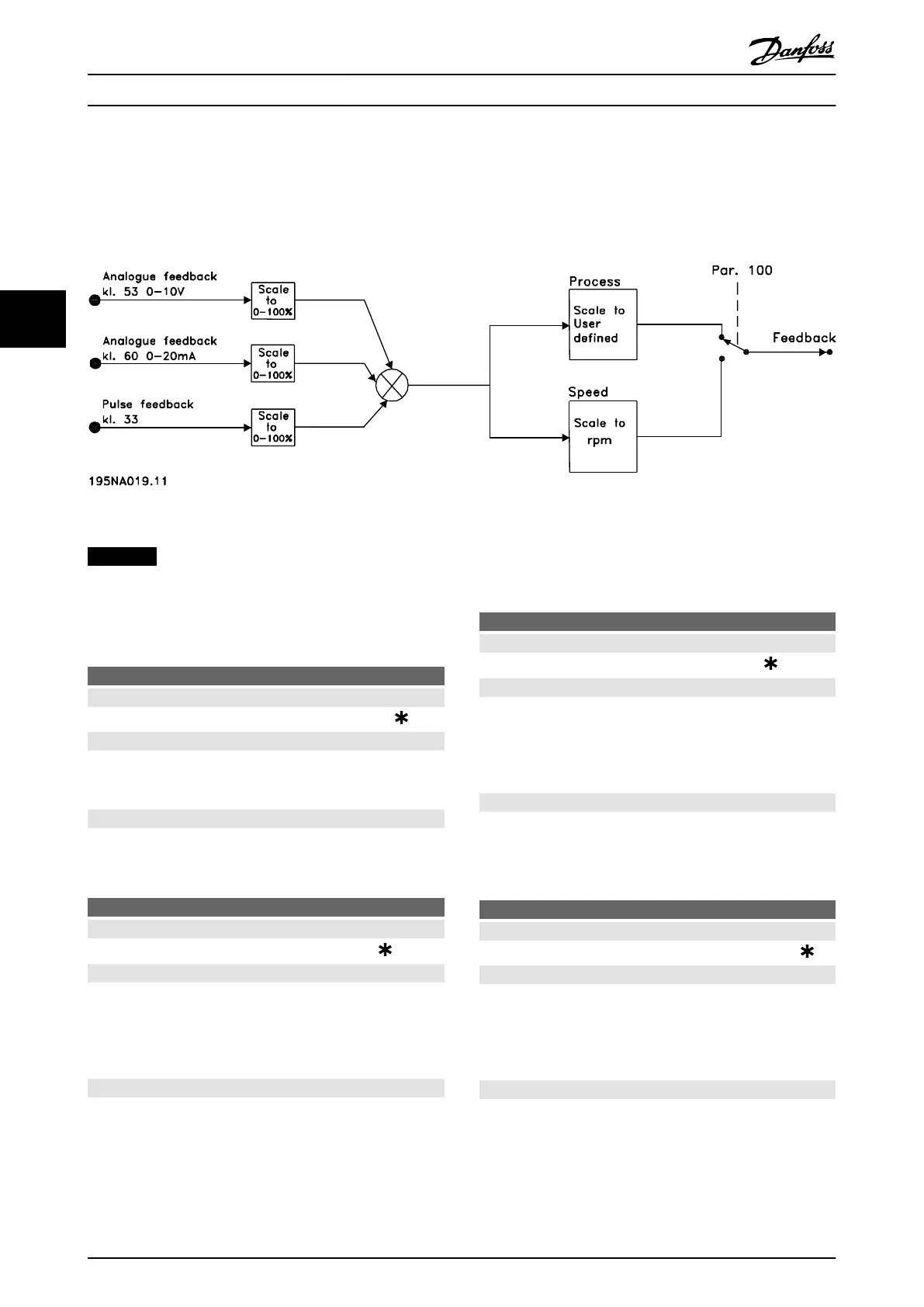
4.5.3 Handling of Feedback
Feedback handling is shown in Illustration 4.16.
The flowchart shows which parameters can affect the handling of feedback and how. Select between voltage, current and
pulse feedback signals.
Illustration 4.16 Feedback Handling
NOTICE
Parameters 417-421 are only used, if in parameter 100
Configuration the selection made is [1] Speed regulation,
closed loop.
417 Speed PID proportional gain
Value:
0.000 (OFF) - 1.000
0.010
Function:
Proportional gain indicates how many times the fault
(deviation between the feedback signal and the setpoint)
is to be amplified.
Description of choice:
Quick regulation is obtained at high amplification, but if
the amplification is too high, the process may become
unstable in the case of overshooting.
418
Speed PID integral time
Value:
20.00 - 999.99 ms (1000 = OFF)
100 ms
Function:
The integral time determines how long the PID regulator
takes to correct the error. The greater the error, the
quicker the integrator frequency contribution increases.
The integral time is the time the integrator needs to
achieve the same change as the proportional amplification.
Description of choice:
Quick regulation is obtained through a short integral time.
However, if this time is too short, it can make the process
unstable. If the integral time is long, major deviations from
the required reference may occur, since the process
regulator takes long to regulate if an error has occurred.
419 Speed PID differential time
Value:
0.00 (OFF) - 200.00 ms
20.00 ms
Function:
The differentiator does not react to a constant error. It only
makes a contribution when the error changes. The quicker
the error changes, the stronger the gain from the differen-
tiator is. The contribution is proportional to the speed at
which errors change.
Description of choice:
Quick control is obtained by a long differential time.
However, if this time is too long, it can make the process
unstable. When the differential time is 0 ms, the D-function
is not active.
420
Speed PID D- gain limit
Value:
5.0 - 50.0
5.0
Function:
It is possible to set a limit for the gain provided by the
differentiator. Since the D-gain increases at higher
frequencies, limiting the gain may be useful. This enables
obtaining a pure D-gain at low frequencies and a constant
D-gain at higher frequencies.
Description of choice:
Select the required gain limit.
Programming Design Guide
96 Danfoss A/S © Rev. May/2014 All rights reserved. MG27E402
44

 Loading...


