•
•
•
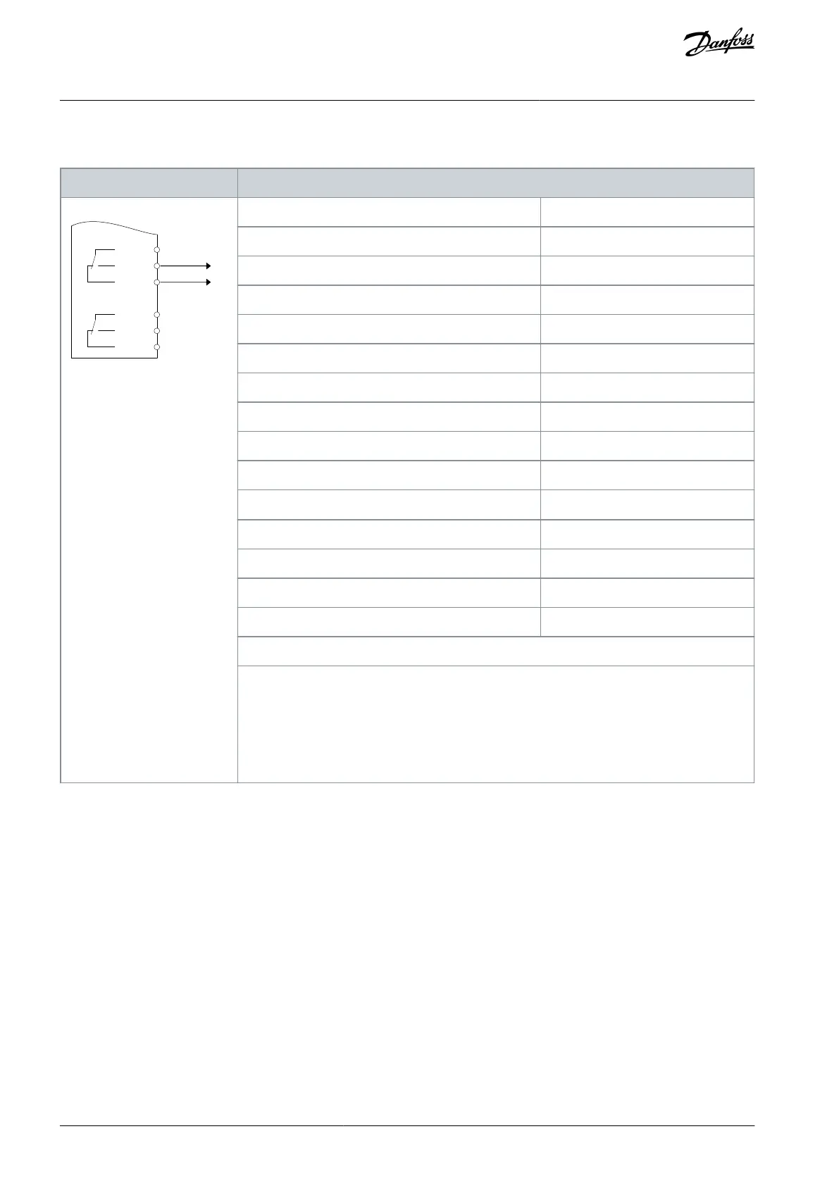
8.1.11 Wiring Conguration for a Relay Set-up with Smart Logic Control
Table 89: Wiring Conguration for a Relay with Smart Logic Control
XD2.21
XD2.22
XD2.23
XD2.24
XD2.25
XD2.26
Parameter 4-30 Motor Feedback Loss Function
Parameter 4-31 Motor Feedback Speed Error
Parameter 4-32 Motor Feedback Loss Timeout
Parameter 7-00 Speed PID Feedback Source
Parameter 17-11 Resolution (PPR)
Parameter 13-00 SL Controller Mode
Parameter 13-01 Start Event
Parameter 13-02 Stop Event
Parameter 13-10 Comparator Operand
Parameter 13-11 Comparator Operator
Parameter 13-12 Comparator Value
Parameter 13-51 SL Controller Event
Parameter 13-52 SL Controller Action
[32] Set digital out A low
Parameter 5-40 Function Relay
Notes/comments:
If the limit in the feedback monitor is exceeded, warning 90, Feedback Mon. is issued. The SLC
monitors warning 90, Feedback Mon. and if the warning becomes true, relay 1 is triggered. Exter-
nal equipment may require service.
However, if the feedback error goes below the limit again within 5 s and the warning disap-
pears, press [Reset] on the LCP.
8.1.12 Wiring Conguration for a Submersible Pump
The system consists of a submersible pump controlled by a Danfoss VLT
®
AQUA Drive and a pressure transmitter. The transmitter
gives a 4–20 mA feedback signal to the drive, which keeps a constant pressure by controlling the speed of the pump. To design a
drive for a submersible pump application, there are a few important issues to consider. Select the drive according to motor current.
The CAN motor is a motor with a stainless steel can between the rotor and stator that contains a larger and a more magnetic
resistant air-gap than on a normal motor. This weaker eld results in the motors being designed with a higher rated current than
a normal motor with similar rated power. The special CAN motor is used because of the wet installation conditions. Design the
system according to output current to be able to run the motor at nominal power.
The pump contains thrust bearings that are damaged when running below minimum speed, which is normally 30 Hz.
The motor reactance is nonlinear in submersible pump motors and, therefore, automatic motor adaption (AMA) may not be
possible. Normally, submersible pumps are operated with long motor cables that might eliminate the nonlinear motor reac-
tance and enable the drive to perform AMA. If AMA fails, the motor data can be set from parameter group 1-3* Adv. Motor Data
(see the motor datasheet). If AMA has succeeded, the drive compensates for the voltage drop in the long motor cables. If the
advanced motor data are set manually, consider the length of the motor cable to optimize system performance.
AQ262141056213en-000201 / 130R0882114 | Danfoss A/S © 2020.09
Wiring Conguration Examples
VLT® AQUA Drive FC 202
Operating Guide

 Loading...


