Radio frequency interference (RFI) lter
Passive harmonic lter (PHF) L0
Molded-case circuit breaker (MCCB)
dU/dt and sine-wave lter fans
Sine-wave lter capacitor
11.6 Input Power Option Losses
The loss values shown in this section are typical of the worst case operating conditions. For normal conditions, typical power loss is
expected to be within ±15%. The tolerance relates to dierences in voltage and cable conditions. These values are based on a typi-
cal motor eciency (IE/IE3 border line). Lower eciency motors increase power loss in the drive and lters, which aect the dimen-
sioning of the drive and lter cooling. If the switching frequency is higher than the default setting, the power losses can increase.
For output lters, an increase in motor frequency will increase the losses. In this situation, follow the derating guidelines specied in
the product-specic Design Guide.
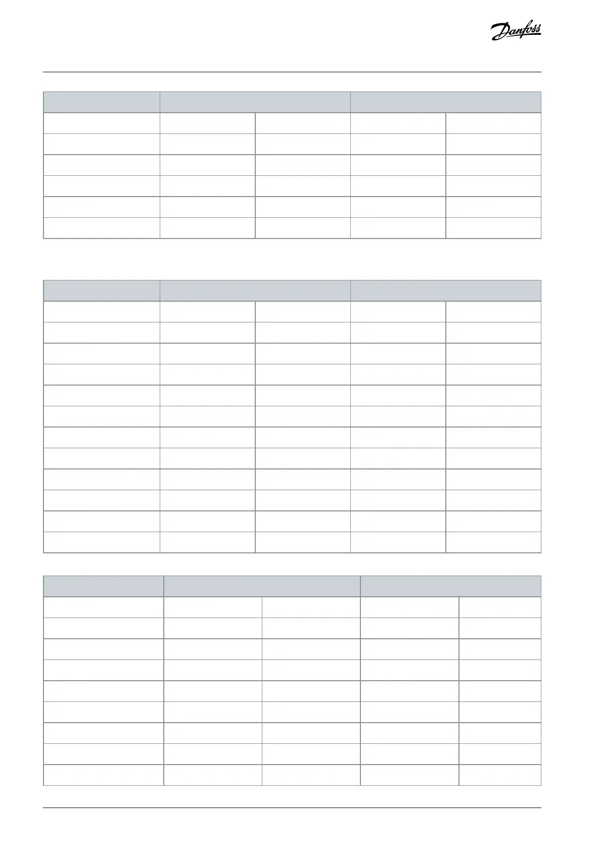
11.6.1 Contactor Losses
Table 142: Power Losses for Contactor Option, 380–480 V (Losses Shown in Watts)
Table 143: Power Losses for Contactor Option, 525–690 V (Losses Shown in Watts)
AQ262141056213en-000201 / 130R0882178 | Danfoss A/S © 2020.09
Appendix
VLT® AQUA Drive FC 202
Operating Guide

 Loading...


