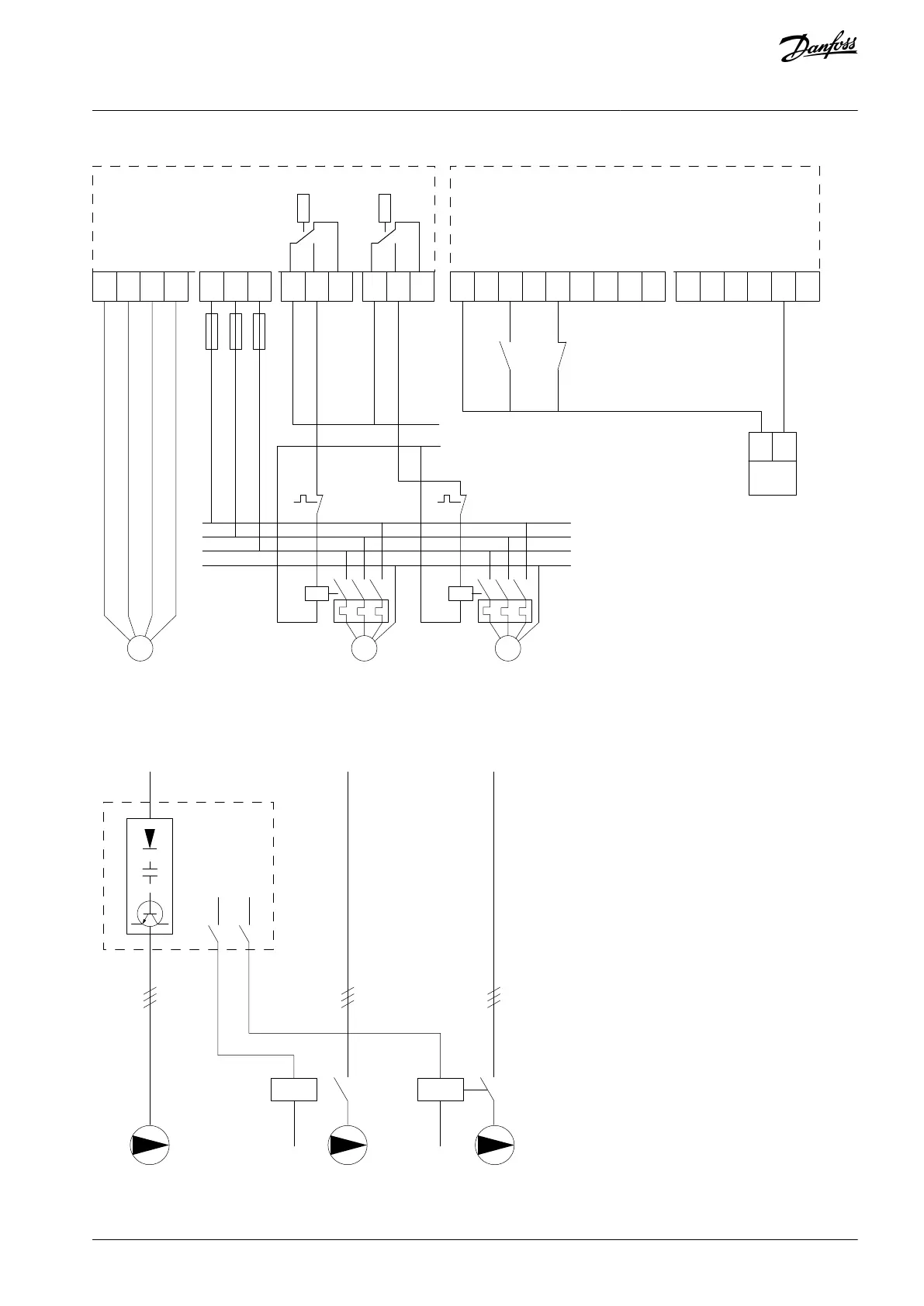
Control compartment/control card
System
start/
stop
From motor control circuitry
System
safety
interlock
Pressure
transmitter
4-20 mA,
L1
D IN1
D IN1/D OUT
D IN1/D OUT
D IN 1
D IN 1
A IN2
A OUT1
COM A OUT
+ 10 V OUT
A IN1
COM A IN
96
U
97
V
98
W
PE
91
L1
92
L2
93
L3
XD2.
21
XD2.
22
XD2.
23
XD2.
24
XD2.
25
XD2.
26
XD2.
10
XD2.
11
XD2.
12
XD2.
13
XD2.
14
XD2.
15
XD2.
16
XD2.
17
XD2.
18
XD2.
4
XD2.
5
XD2.
6
Illustration 63: Cascade Controller Wiring Diagram
8.1.14 Wiring Conguration for a Fixed Variable Speed Pump
Illustration 64: Fixed Variable Speed Pump Wiring Diagram
AQ262141056213en-000201 / 130R0882 | 117Danfoss A/S © 2020.09
Wiring Conguration Examples
VLT® AQUA Drive FC 202
Operating Guide

 Loading...


