•
•
It is important that the system is operated with a minimum of wear and tear on the pump and motor. A Danfoss sine-wave lter
can lower the motor insulation stress and increase lifetime (check actual motor insulation and the drive dU/dt specication).
Most manufacturers of submersible pumps require the use of output lters.
EMC performance can be dicult to achieve because the special pump cable, which is able to withstand the wet conditions in
the well, is normally unshielded. A solution could be to use a shielded cable above the well and attach the shield to the well
pipe, if it is made of steel. A sine-wave lter also reduces the EMI from unshielded motor cables.
To prevent damage to the thrust bearings of the pump, and to ensure sucient motor cooling as quickly as possible, it is important
to ramp the pump from stop to minimum speed as quickly as possible. Most submersible pump manufacturers recommend that the
pump ramps to minimum speed (30 Hz) in maximum 2–3 s. The VLT
®
AQUA Drive FC 202 is designed with initial and nal ramp for
these applications. The initial and nal ramps are 2 individual ramps, where initial ramp, if enabled, ramps the motor from stop to
minimum speed and automatically switches to normal ramp, when minimum speed is reached. Final ramp does the opposite from
minimum speed to stop in a stop situation. Consider also enabling advanced minimum speed monitoring.
To achieve extra pump protection, use the dry-run detection function. For more information, see the Programming Guide.
Pipe-ll mode can be enabled to prevent water hammering. The Danfoss drive can ll the vertical pipes using the PID controller to
ramp up the pressure slowly with a user-specied rate (units/second). If enabled, the drive enters pipe-ll mode when it reaches
minimum speed after start-up. The pressure is slowly ramped up until it reaches a user-specied lled setpoint, where the drive
automatically disables pipe ll mode and continues in normal closed-loop operation.
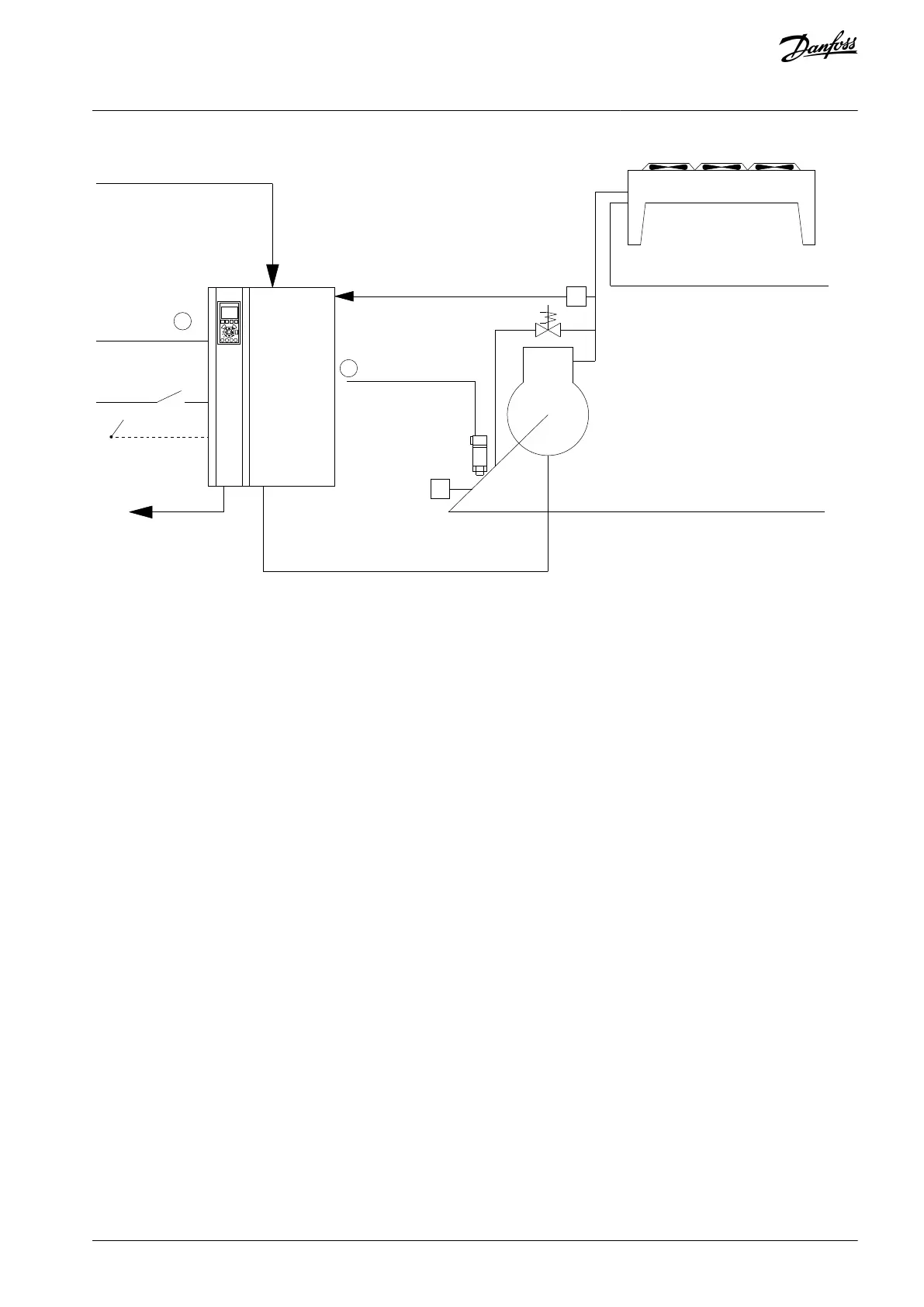
e30bu097.10
M
Ground
L1
L3
T1
T2
T3
XD2.10
XD2.20
XD2.14
XD2.11
XD2.8
L2
Ground
Mains
2 wire 4-20 mA
Pressure
transmitter
Start
Stop
Illustration 61: Wiring for Submersible Pump Application
N O T I C E
Set the analog input 2, (terminal XD2.8) format to mA (switch 202).
Parameter settings
Table 90: Relevant Parameters for Submersible Pump Application
Parameter 1-20 Motor Power [kW]/parameter 1-21 Motor Power [HP]
Parameter 1-22 Motor Voltage
Parameter 1-24 Motor Current
Parameter 1-28 Motor Rotation Check
Parameter 1-29 Automatic Motor Adaptation (AMA) = [2] Enable Reduced AMA
Table 91: Example of Settings for Submersible Pump
Parameter 3-02 Minimum Reference
The minimum reference unit matches the unit in parameter 20-12 Reference/ Feed-
back Unit
AQ262141056213en-000201 / 130R0882 | 115Danfoss A/S © 2020.09
Wiring Conguration Examples
VLT® AQUA Drive FC 202
Operating Guide

 Loading...


