If the amount of kinetic energy transferred to the resistor in each braking period is not known, the average power can be calculated
based on the cycle time and braking time, also called intermittent duty cycle. The resistor intermittent duty cycle is an indication of
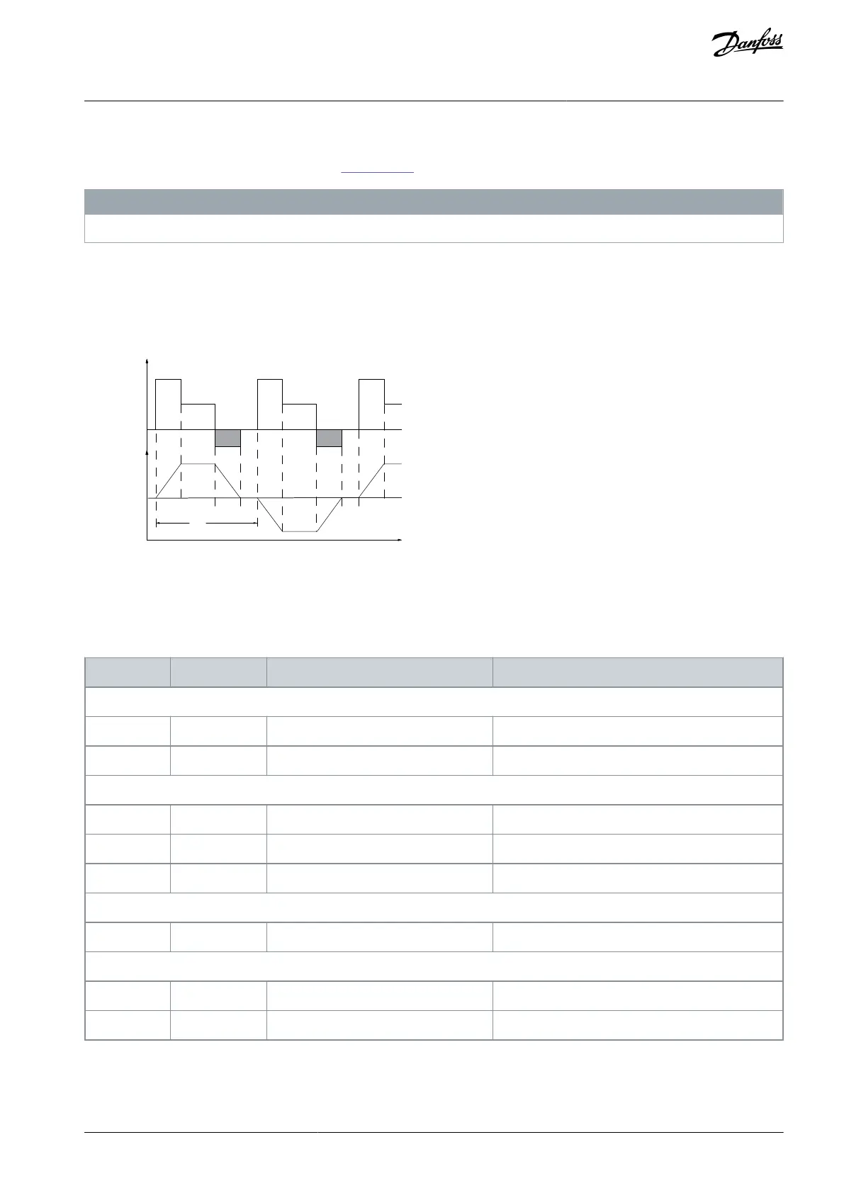
the duty cycle at which the resistor is active. See Illustration 74 for a typical braking cycle.
N O T I C E
Motor suppliers often use S5 when stating the allowed load, which is an expression of intermittent duty cycle.
The intermittent duty cycle for the resistor is calculated as follows:
Duty cycle=t
b
/T
T=cycle time in s.
t
b
is the braking time in s (of the cycle time).
Illustration 74: Dynamic Braking Cycle Time
Brake resistors have a duty cycle of 5%, 10%, and 40%. If a 10% duty cycle is applied, the brake resistors are able to absorb brake
power for 10% of the cycle time. The remaining 90% of the cycle time is spent on dissipating excess heat.
Table 87: Braking at High Overload Torque Level
Braking duty cycle at 100% torque
Braking duty cycle at overtorque (150/160%)
AJ300847815559en-000101 / 130R0337 | 139Danfoss A/S © 2020.09
Electrical Installation
Considerations
VLT® AQUA Drive FC 202
Design Guide

 Loading...


