FC 300 Design Guide
How to Install
" Additional Connections
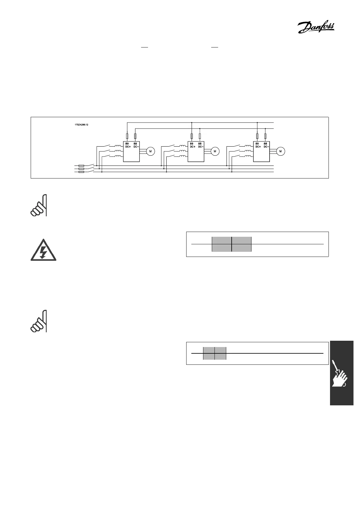
" Load sharing
With load sharing several adjustable frequency drives’ DC interme diat e circuits can be connected together
which will extend the installation if extra fuses and AC coils are used (see illustration).
NOTE
Load sharing ca bles must be shielded/armoured. If an unshielded/unarmoured cable
is used, some EMC requirements are not compl ied with.
Voltage levels of up to 975 V DC may
occur between terminals 88 and 89.
No. 88 89 Loadsharing
DC DC +
" Installation of Load Sharing
The connection cable must be shielded and the maximum length from the adjust able
frequency drive to the DC bar is 82 ft (25 m).
NOTE
Load sharing calls for extra equipment. For further information, see Load-
sharing Instructions MI.50.NX.YY.
" Brake Connection Option
The connection cable to the brake resistor
must be shielded/armored.
No. 81 82 Brake resistor
R- R+ te rminals
1. Use ca
ble clamps to connect the shield to the metal cabinet of the adjustable frequency
drive and to the decoupling plate of the brake resistor.
2. Dimension the cross-se ction of the brake cable to match the brake current.
101
MG.33.B3.22 - VLT is a registered Danfoss trademark
 Loading...


