FC 300 Design Guide
Introduction to FC 300
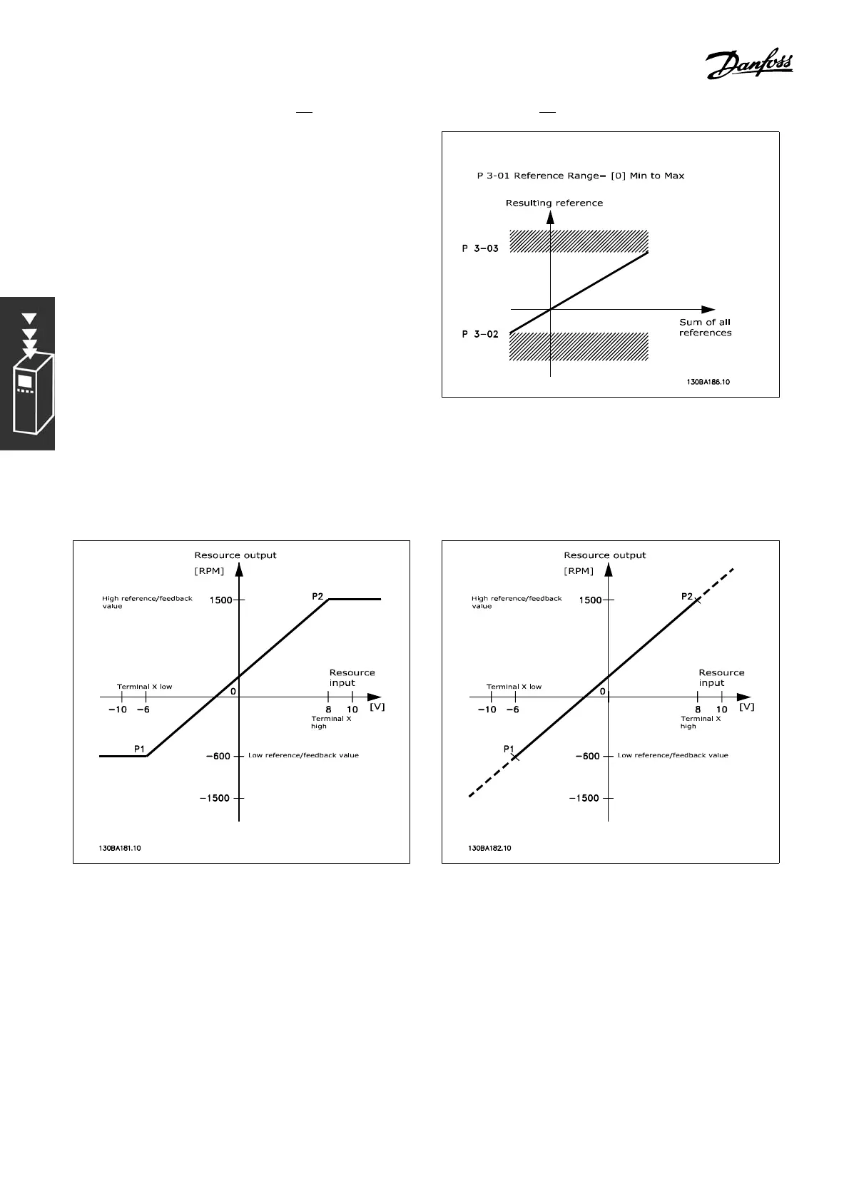
The value of par. 3-02 Minimum Reference
can not be set to less than 0, unless par. 1-00
Configuration Mode is set to [3] Process. In
this case, the subsequent relations between the
resulting reference (after clamping) and the sum
of all references are as shown to the right.
References and feedback are scaled from analog and pulse inputs in the same way. The only difference
is that a reference above or below the specified minimum and maximum "endpoints" (P1 and P2 in
the graph below) are clamped whereas a feedback above or below is not.
The endpoints P1 and P2 are defined by the following parameters, depending on
which analog or pulse i nput is used
26
MG.33.B3.22 - VLT is a registered Danfoss trademark
 Loading...


