FC 300 Design Guide
Introduction to FC 300
Optimization of the process regulator
The basic settings have now been made; all that needs to be d one is to optimize the proportional
gain, the integration time, and the differentiation time (par. 7-33, 7-34, 7-35). In most
processes, this can be done by following the guidelines given below.
1. Start the motor
2. Set par. 7-33 (Proportional Gain) to 0.3 and increase it until the feedback signal again
begins to vary continuously. Then reduce the value until the feedback signal has
stabilized. Now lower the proportional gain by 40-60%.
3. Set par. 7-34 (Integral Time) to 20 sec. and reduce the value until the feedback signal
again begins to vary continuously. Increase the inte gration time until the feedback
signal stabilize s, followed by an increase o f 15-50%.
4. Only use par. 7 -35 for very fast-acting systems (differentiation time). The typical value is f
our times
the set integral time. The differentiator should only be used when the setting of the proportional
gain and the integral time has been fully optimized. Make sure that oscillations in the feedback
signal are sufficiently damped by the low-pass filter on the feedback signal.
NOTE
If necessary, start/s top can be activated a number of times in order to provoke
a variation of the feedback signal.
" Ziegler Nichols Tuning Method
In order to tune the PID controls of the adjustable frequency drive, several tuning methods
can be used. One approach is to use a technique which was developed in the 1950s but which
has stood the test of time and is still use d today. This meth
od is known as the Ziegler Nichols
tuning method and it can be considered "quick and dirty."
NOTE
The method described must not be used on applications that could be damaged by the
oscillations created by marginally stable con
trol settings.
The criteria for adjusting the parameters ar
ebased
on evaluating the system at the limit of stability
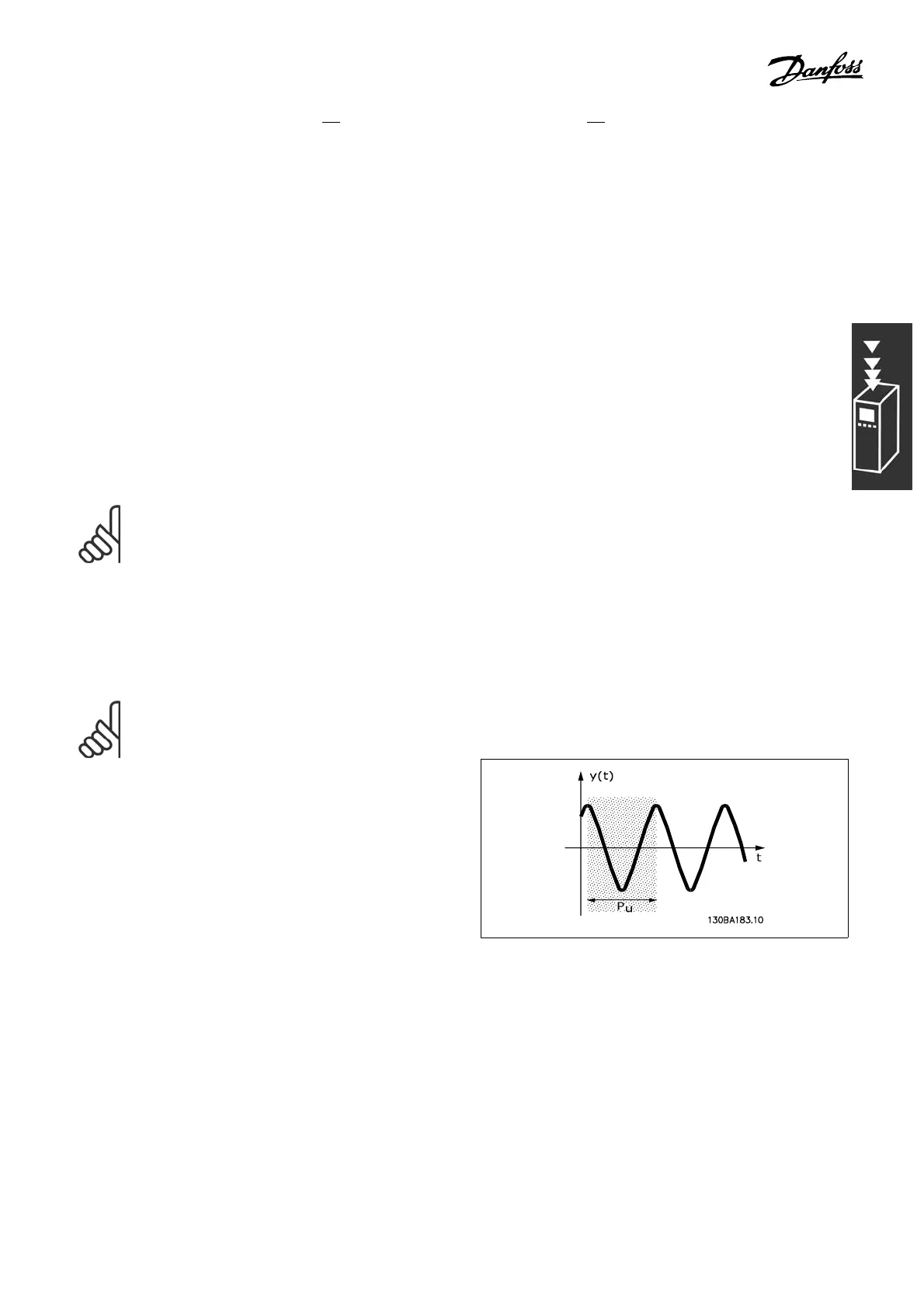
rather than on taking a step response. We increase
the proportional gain until we observ
e continuous
oscillations (as measured on the fe edb ack), that is,
until the system becomes marginally stable. The
corresponding gain (called the ul
timate gain) and
the period of oscil lation (also called the ultim ate
period) are determined as shown in Figure 1.
Figure 1: Marginally stable syste m
P
u
should be measured when the amplitude of oscillation is quite small. Then we "back
off " from this gain again, as shown in Table 1.
41
MG.33.B3.22 - VLT is a registered Danfoss trademark
 Loading...


