FC 300 Design Guide
How to Program
" Display Mode
In normal operation, up to 5 different operating variables can be indicated continuously in
the middle section: 1 .1, 1.2, and 1.3 as well as 2 and 3.
" Display Mode - Selection of Read-Outs
It is possible to toggle between three status readout
screens by pressing the [Status] key.
Operating variables with different formatting are
shownineachstatusscreen-seebelow.
The table shows the measurements you can link to
each of the o perating variables. Define t he links
via par. 0-20, 0-21, 0-22, 0-23, and 0-24.
Each readout parameter selected in par. 0-20
to par. 0-24 ha s its own scale and digits after
a possible decim al point. By larger numeric
value of a parameter fewer digits are displayed
after the decimal point.
Ex.: Current readout
5.25 A; 15.2 A 105 A.
Operating variable: Unit:
Par. 16-00 Control Word hex
Par. 16-01 Reference [unit]
Par. 16-02 Reference %
Par. 16-03 Status word hex
Par. 16-04 Alarm word hex
Par. 16-05 Warning word hex
Par. 16-06 Extended status wordhex [%]
Par. 16-10 Power [kW]
Par. 16-11 Power [HP]
Par. 16-12 Motor voltage [V]
Par. 16-13 Frequency [Hz]
Par. 16-14 Motor current [A]
Par. 16-16 Torque Nm
Par. 16-17 Speed [RPM]
Par. 16-18 Motor thermal %
Par. 16-20 Phase angle
Par. 16-30 DC link voltage V
Par. 16-32 Brake energy / s kW
Par. 16-33 Brake energy / 2 min kW
Par. 16-34 Heatsink temp. C
Par. 16-35 Inverter thermal %
Par. 16-36 InomVLT A
Par. 16-37 ImaxVLT A
Par. 16-38 SL controller state
Par. 16-39 Control card temp. C
Par. 16-50 External reference
Par. 16-51 Pulse reference
Par. 16-52 Feedback [Unit]
Par. 16-60 Digital input bin
Par. 16-61 Terminal 53 switch setting V
Par. 16-62 Analog input 53
Par. 16-63 Terminal 54 switch setting V
Par. 16-64 Analog input 54
Par. 16-65 Analog output 42 [mA]
Par. 16-66 Digital output [bin]
Par. 16-67 Freq. input #29 [Hz]
Par. 16-68 Freq. input #33 [Hz]
Par. 16-69 Pulse output #27 [Hz]
Par. 16-70 Pulse output #29 [Hz]
Par. 16-80 Fieldbus CTW hex
Par. 16-82 Fieldbus REF hex
Par. 16-83 Fieldbus MAV hex
Par. 16 -84 Comm. option STW hex
Par. 16-85 FC port CTW 1 hex
Par. 16-86 FC port REF 1 hex
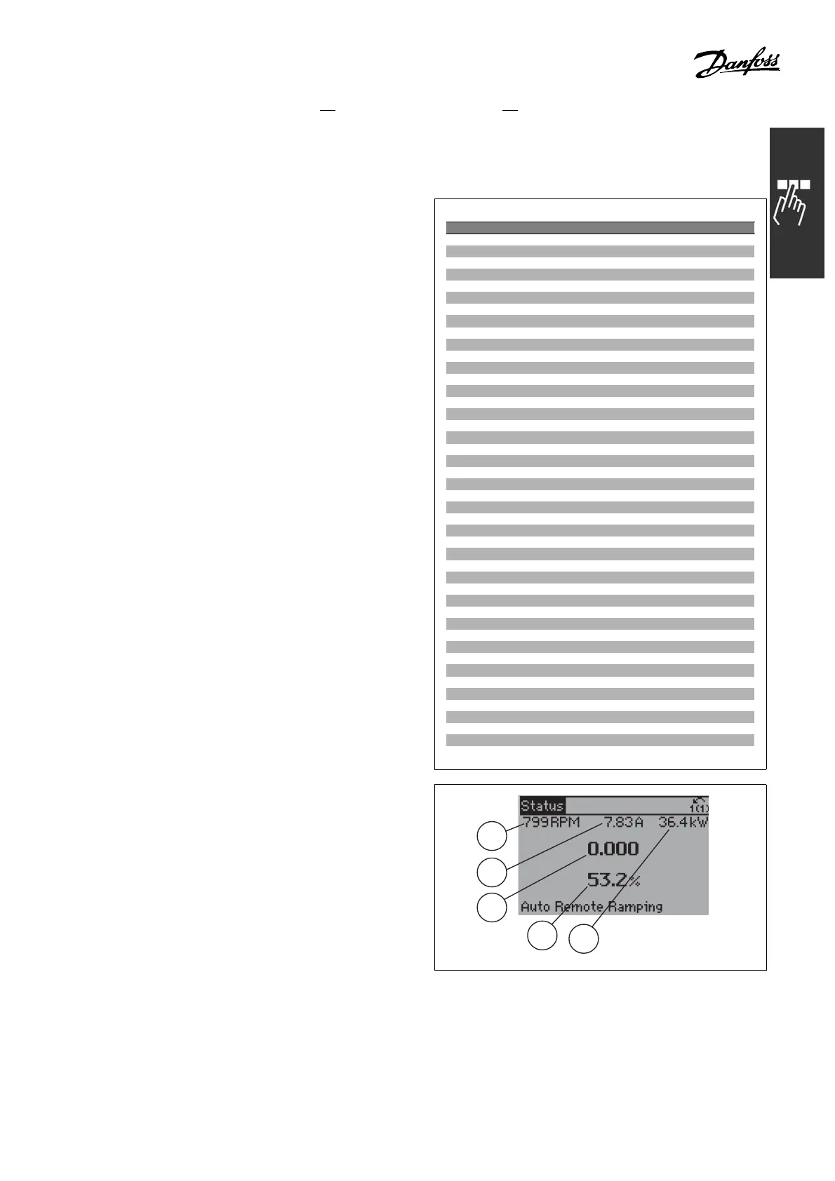
Status screen I:
This readout state is standard after start-up
or initialization.
Use [INFO] to obtain information about the
measurement links to the displayed operating
variables /1.1, 1.2, 1.3, 2, and 3).
See the operating variables shown in the
screen in this illustration.
130BP041.10
1.1
1.3
2
1.2
3
125
MG.33.B3.22 - VLT is a registered Danfoss trademark
 Loading...


