FC 300 Design Guide
How to Install
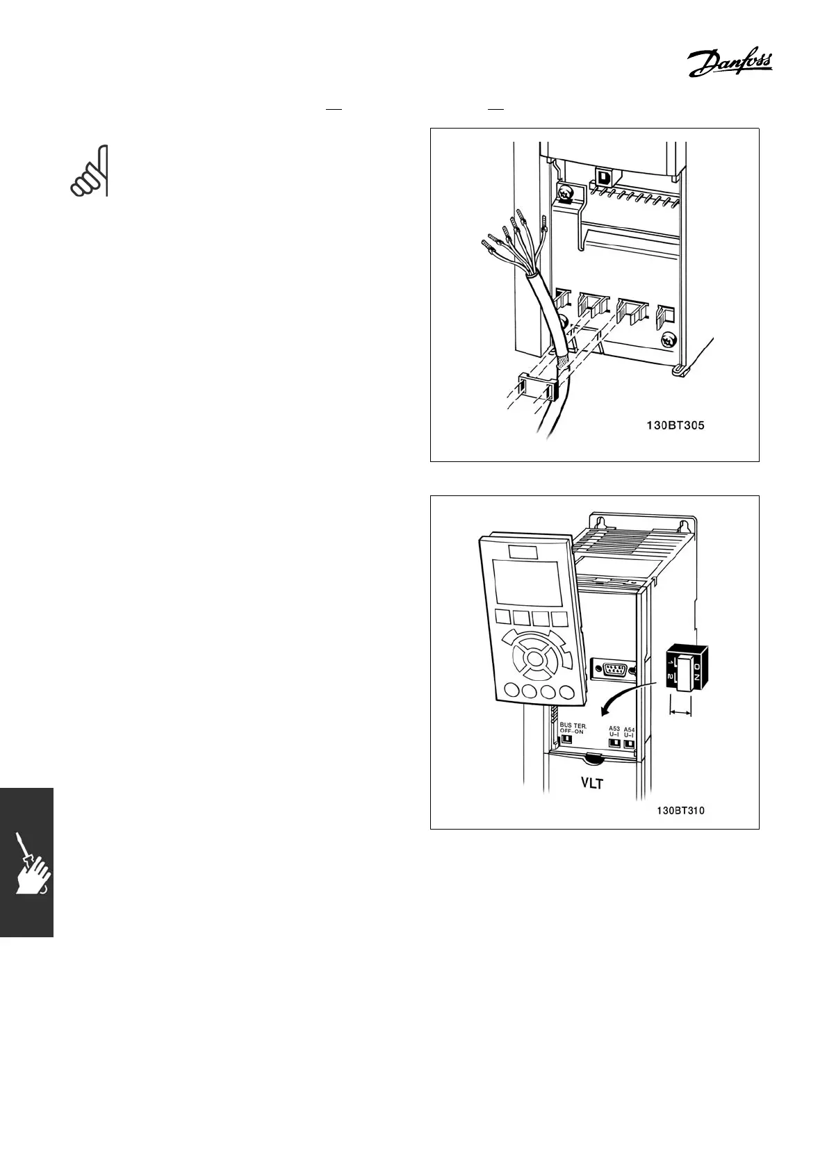
NOTE
Control cables must be shielded/armored.
1. Use a clamp from the accessory bag to
connect the shield to the FC 300 grounding
plate for control cables.
See section entitled Grounding of Shielded/Armored
Control Cables for the correct termination
of control cables.
" Switches S201, S202, and S801
Switches S201 (A53) and S2 02 (A54) are used
to select a current (0-20 mA) or a voltage
(-10 to 10 V) configuration of the anal
og input
terminals 53 and 54 res pectively.
Switch S801 (BUS TER.) can be used to
enable termination on the RS-485 port
(terminals 68 and 69).
See drawing Diagram showing
all electrical
terminals in section Electrical Installation.
Default setting:
S201 (A53) = OFF (voltage input)
S202 (A54) = OFF (voltage input)
S801 (Bus termination) =
OFF
96
MG.33.B3.22 - VLT is a registered Danfoss trademark
 Loading...


