EasyManuals Logo
Home>Danfoss>DC Drives>VLT AutomationDrive FC 300 Series

Danfoss VLT AutomationDrive FC 300 Series Design Guide

Danfoss VLT AutomationDrive FC 300 Series
275 pages
To Next Page IconTo Next Page
To Previous Page IconTo Previous Page
Page #84 background imageLoading...
Page #84 background image
FC 300 Design Guide
How to Install
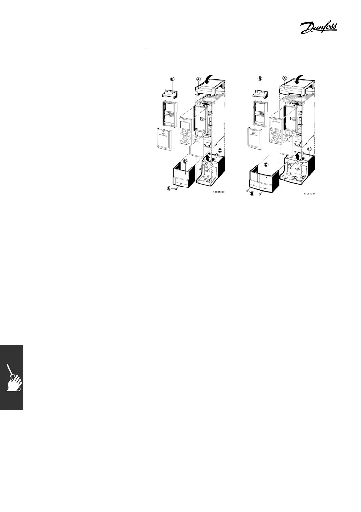
" IP 21/Type 1 (N E M A 1) Enclosure Kit
A-Topcover
B-Brim
C-Basepart
D-Basecover
E-Screw(s)
Place the top cover as shown. If an A or B option
is used the brim must be fitted to c over the top
inlet. Place the base part C at the bottom of the
drive and use the clamps from the accessory bag
to correctly fasten the cables. Holes for cable
glands:
Size A2: 2x PG16 (½") 3xPG21 (3/4")
Size A3: 3xPG16 ( ½") 3xPG21 (3/4")
84
MG.33.B3.22 - VLT is a registered Danfoss trademark

Table of Contents

Other manuals for Danfoss VLT AutomationDrive FC 300 Series

Questions and Answers:

Question and Answer IconNeed help?

Do you have a question about the Danfoss VLT AutomationDrive FC 300 Series and is the answer not in the manual?

Danfoss VLT AutomationDrive FC 300 Series Specifications

General IconGeneral
BrandDanfoss
ModelVLT AutomationDrive FC 300 Series
CategoryDC Drives
LanguageEnglish

Related product manuals