FC 300 Design Guide
Introduction to FC 300
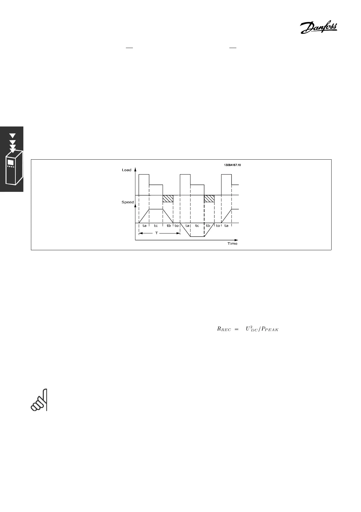
" Selection of Brake Resistor
To select the right brake resistor, it is necessary to know how often to brake and by
how much the power braking is effected.
The resistor intermittent duty (S 5), which is often used by motor suppliers when stating the permissible
load, is an indication of the duty cycle a t which the resistor is working.
The intermittent duty cycle for the res istor is calculate d as follows, in which T = cycle time in
seconds and t
b
is the braking time in seconds (of the cycle time): The max. permissible load
on the brake resistor is stated as a peak power at a given intermittent duty cycle. Therefore,
determine the peak pow er for the brake res istor and the resistor value.
Dutycycle = T
b
/T
The max. permissible load on the brake resistor is stated as a peak power at a given ED. Therefore,
determine the peak pow er for the brake resi
stor and the resistor value.
The shown example and formula apply to FC 3
02.
P
PEAK
=P
MOTOR
xM
BR(%)
x η
MOTOR
x η
VLT
[W]
The brake resistance is calculated as shown
:
As can be seen, the brake resistance depends on the intermed iate circuit voltage (UDC).
With FC 302 adjustable frequency drives with a line voltage of 3 x 200-240 V, the brake will
be active at 390 V (UDC). If the adjustable frequency drive has a line voltage of 3 x 380-500
V, the brake will be active at 81 0 V (UDC), and if the adjustable frequency drive has a line
voltage of 3 x 525-600 V, the brake will be active at 943 V (UDC).
NOTE
Check that the brake resistor can cope with a voltage of 430 V, 850 V or 930 V
- unless Danfoss brake resistors are used.
48
MG.33.B3.22 - VLT is a registered Danfoss trademark
 Loading...


