FC 300 Design Guide
Introduction to FC 300
" Galvanic Isolation (PELV)
PELV offers protection by way of extra low voltage. Protection against electric shock is
ensured when the electrical supply is of the PELV type and the installation is made as
described in local/national reg u lations on PELV supplies.
All control terminals and relay terminals 0 1-03/04-06 comply with PELV (Protective Extra Low Voltage)
(Does not app ly to 525-600 V units a nd at grounded Delta leg above 300 V).
Galvanic (ensure d) isolation is obtained by fulfilling requirements for higher isolation and by providing the
relevant creepage/clearance distances. These requirements are described in the EN 61 800-5-1 standard .
The components that make up the electrical isolation, as described below, also comply with the
requirements for higher isolation and the relevant test as describe d in EN 61800-5-1.
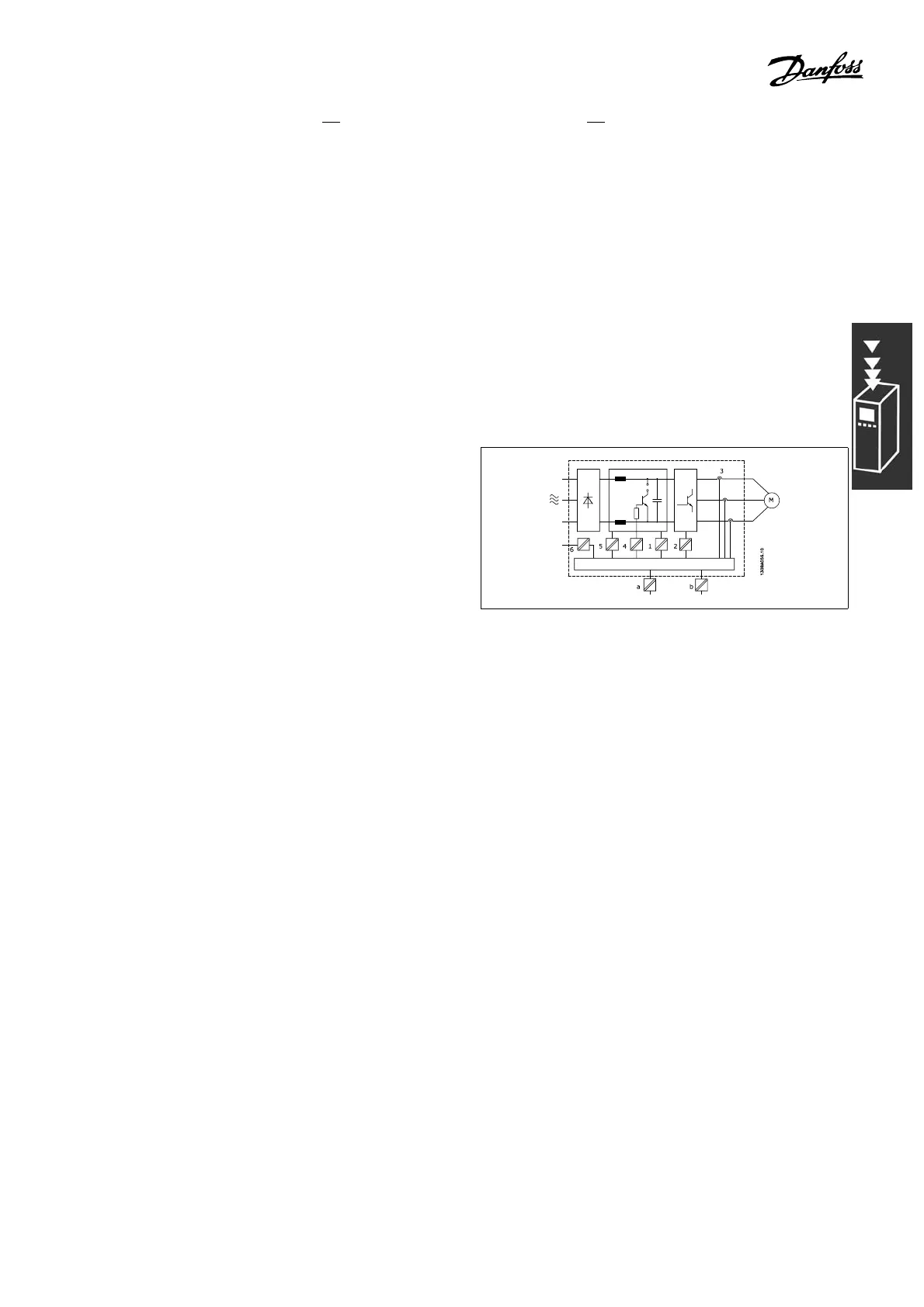
The PELV galvanic isolation ca n be shown in six locations (see illustration):
1. Power supply (SM PS) incl. signal isolation of
U
DC
, indicating the intermediate current voltage.
2. Gate drive that runs the IGBTs (trigger
transformers/opto-couplers).
3. Current transducers.
4. Opto-coupler, brake module.
5. Internal inrush, RFI, and temperature
measurement circuits.
6. Custom relays.
Galvanic isolation
The functional galvanic isolation (a and b on drawing) is for the 24 V backup option
and for the RS-485 standard bus interface.
51
MG.33.B3.22 - VLT is a registered Danfoss trademark
 Loading...


