FC 300 Design Guide
How to Program
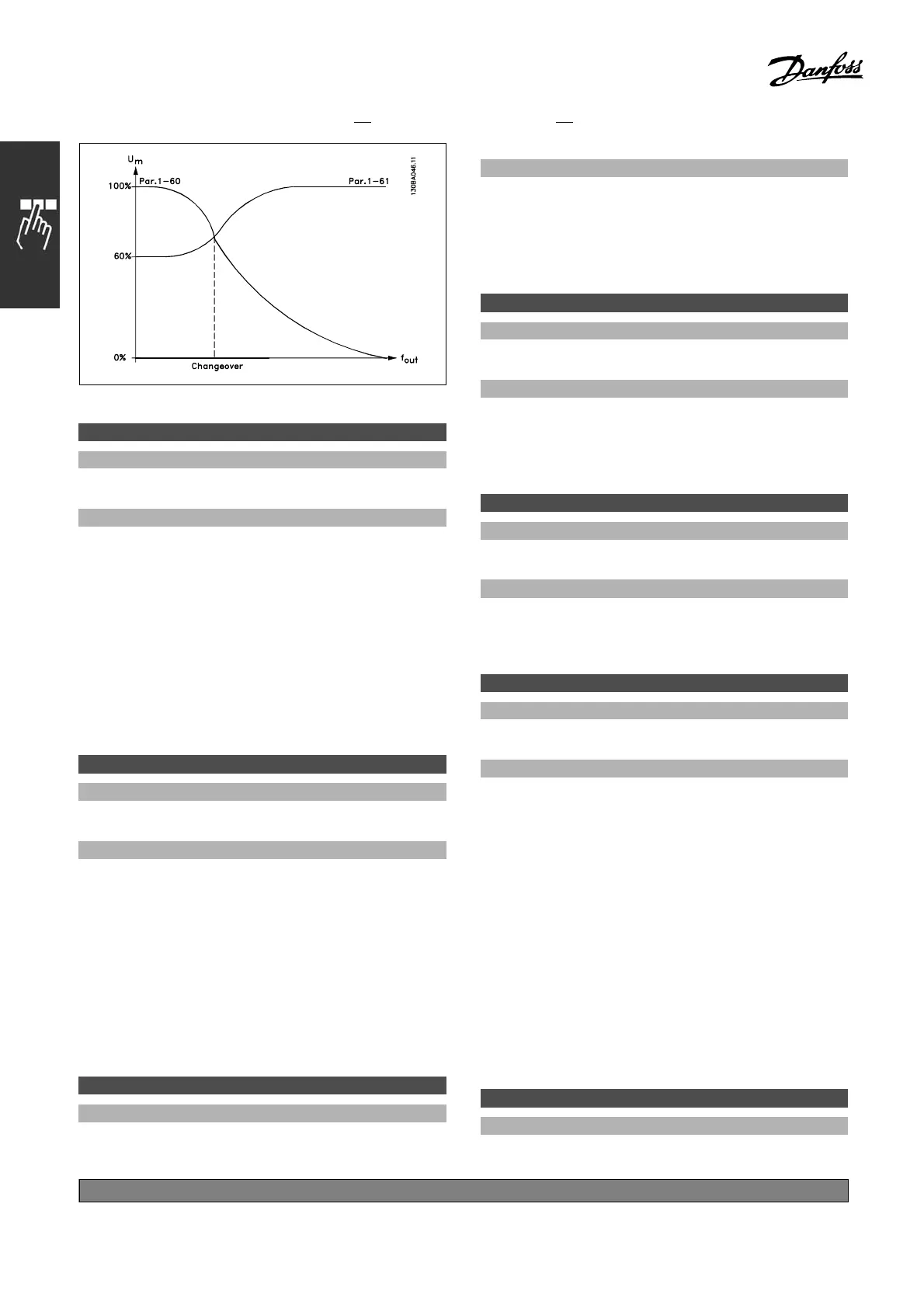
1-61 High Speed Load Compensation
Range:
-300 - 300%
*
100%
Function:
Enables compensation of voltage in relation to
load when the motor is running at high speed.
Optimum U/f characteristic is obtained. The
frequency range within which this parameter is
active, d epends on the motor size.
Motor size Changeover
0.34 - 10 HP (0.25 kW -
7.5 kW)
>10Hz
1-62 Slip Compensation
Range:
-500 - 500 %
*
100%
Function:
Slip compensation is calculated automatically,
i.e. on the basis of the rated motor speed n
M,N
.
In par. 1-62, slip compensation is adjusted in
detail, w hich compensates for tolerances in the
value of n
M,N
. This function is not active along
with Torque Characteristics (par. 1-03), Speed
closed loop, Torque control, Speed feedb ack,
and Special motor characteristics.
Enter a %-value of the rated motor
frequency (par. 1-23).
1-63 Slip Compensation Time Constant
Range:
0.05 - 5.00 s
*
0.10s
Function:
Determines the slip compensation reaction
speed. A high value results in slow reaction.
On the other hand, a low value results in quick
reaction. If low-frequency resonance problems are
encountered, the set time must be longer.
1-64 Resonance Dampening
Range:
0-500%
*
100%
Function:
Setting p ar. 1-64 and par. 1-65 can eliminate
high-frequency resonance problems. For
less resonance oscillation, the value of par.
1-64 must be increased.
1-65 Resonance Dampening Time Constant
Range:
5-50msec.
*
5 msec.
Function:
Setting p ar. 1-64 and par. 1-65 can eliminate
high-frequency resonance problems. Choose the
time constant that provides the best dam pening.
1-66 Min. Current at Low Speed
Range:
0-VariableLimit%
*
100%
Function:
Is enabled when par. 1-00 = SPEED OPEN
LOOP only. The drive runs with constant current
through motor below 10 Hz.
When speed i s above 10 Hz, the motor flux model in
the drive controls the motor. Par. 4-16 and / or par.
4-17 automatically adjusts par. 1-66. The parameter
with the hig hest value adjusts par. 1-66. The current
setting in par. 1-66 is composed of the torque
generating current and the magnetizing current.
Example: Par. 4-16 Torque Limit for Motor
Mode is set to 100% and par. 4-17 Tor que
Limit for Generating Mode is set to 60%.
Par. 1-66 autom atically sets to about 127%,
depending on the motor size.
1-67 Load Type
Option:
*
Passive load [0]
Active load [1]
*
default setting ()display text []value for use in communication via serial communication port
146
MG.33.B
3.22 - VLT is a registered Danfoss trademark
 Loading...


