FC 300 Design Guide
How to Program
(the logical product of the status bits
"running" AND "reverse").
• Drive in hand mode [125 ]: The output goes
high whe never the drive is i n Hand on mode (as
indicatedbytheLEDabove[Handon].
• Driveinautomode[126]: The output go es
high whenever the drive is in Hand on mod e
(as indicated by the LED above [Auto on].
5-30 Terminal 27 Digital Output
*
No operation [0]
5-31 Terminal 29 digital Output
*
No operation [0]
"
5-4* Relays
5-40 Function Relay
Array [8] (Relay 1 [0], Relay 2 [1])
Control word bit 11 [36]
Control word bit 12 [37]
Par. 5-40 holds the same options as par. 5-30
including option 36 and 37.
Function:
• Control word bit 11 [36]: Bit 11 in the
control word controls relay 01. See section
Control Word According to FC Profile (CTW).
This option only app lies for par. 5-40.
• Control word bit 12 [37]: Bit 12 in the control
word controls relay 02. See section Control
Word According to FC Profile (CTW).
Selecting between 2 internal mechanical
relays is an array function.
Ex. par. 5-4* → ’OK’ → Function Relay → ’OK’
→ [0] → ’OK’ → select function
Relayno. 1hasarrayno[0]. Relayno.
2 has array no [1].
When re lay option MCB 105 is fitted in the drive,
the f ollowing sele ction of relays take place:
Relay 7 -> Par. 5-40 [6]
Relay 8 -> Par. 5-40 [7]
Relay 9 -> Par. 5-40 [8]
Relay functions are selected from the same list as
for solid state output functions. See par. 5-3*.
5-41 On Delay, Relay
Array [2] (Relay 01 [0], Relay 0 2 [1])
Range:
0.00 - 600.00 s
*
0.00s
Function:
Allows a delay of the cut-in time o f the relays.
Select between 2 internal mechanical relays in
an array function.See par. 5-40.
5-42 Off Delay, Relay
Array [2] (Relay 01 [0], Relay 02 [1])
Range:
0.00 - 600.00 s.
*
0.00s.
Function:
Enables a delay of the relay cut-out time. Select
between 2 in ternal mechan ical relays in an
array function.See par. 5-40
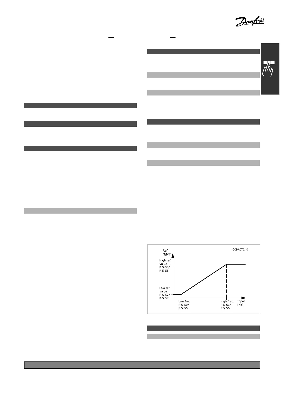
" 5-5* Pulse Input
The p ulse input parameters are used to select
an appropriate window for impulse reference
area. Input terminal 29 or 33 acts as a frequency
reference input. Set par. 5-13 or par 5-15 to "Pulse
input" [32]. If terminal 29 is used as input, par.
5-01 must be selected to "Input" [0].
5-50 Term. 29 Low Frequency
Range:
100 - 110000 Hz
*
100Hz
*
default setting ()display text []value for use in communication via serial communication port
171
MG.33.B
3.22 - VLT is a registered Danfoss trademark
 Loading...


