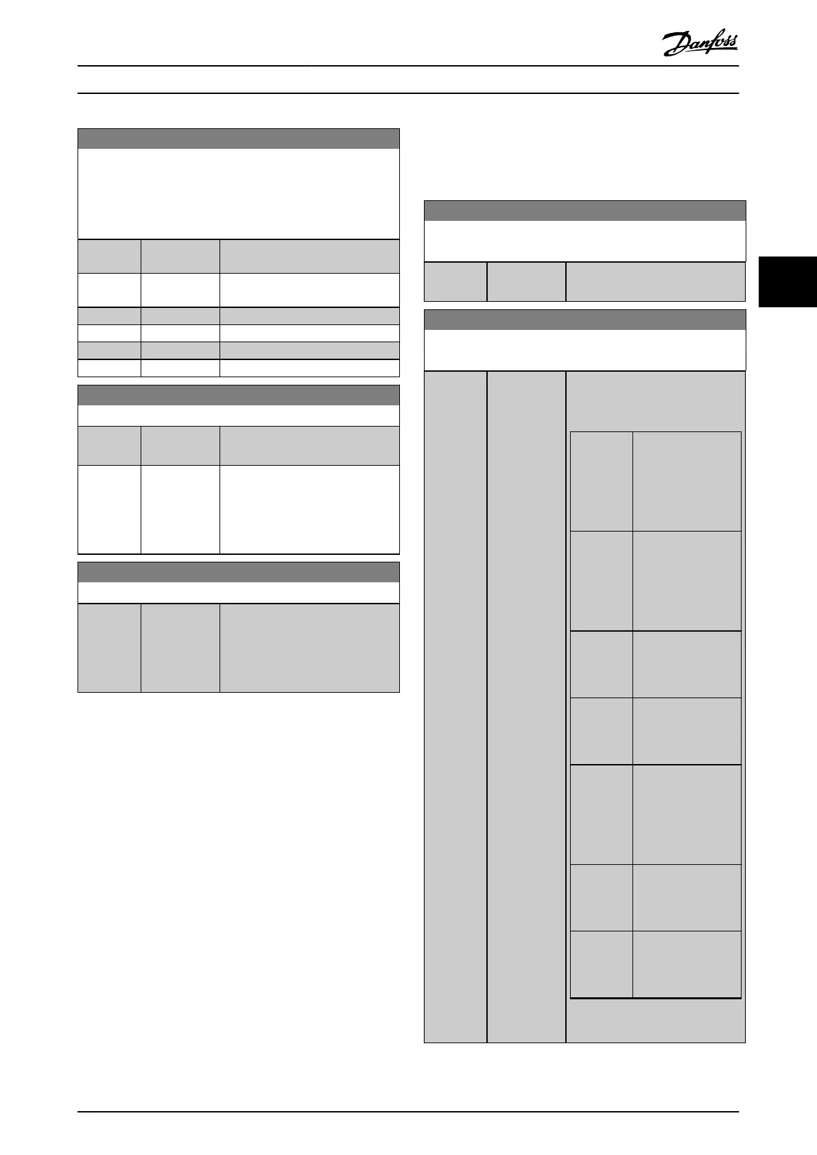
15-12 Trigger Event
Select the trigger event. When the trigger event occurs, a
window is applied to freeze the log. The log then retains a
specied percentage of samples before the occurrence of the
trigger event (parameter 15-14 Samples Before Trigger).
Option: Function:
[37] Digital input
DI32
[38] Digital input
DI33
[50] Comparator 4
[51] Comparator 5
[60] Logic rule 4
[61] Logic rule 5
15-13 Logging Mode
Option: Function:
[0] * Log always Select [0] Log always for continuous
logging.
[1] Log once on
trigger
Select [1] Log once on trigger to
start and stop logging conditionally
using parameter 15-12 Trigger Event
and parameter 15-14 Samples Before
Trigger.
15-14 Samples Before Trigger
Range: Function:
50* [0 - 100] Before a trigger event, enter the
percentage of all samples which
should be retained in the log. See
also parameter 15-12 Trigger Event
and parameter 15-13 Logging Mode.
4.14.3 15-2* Historic Log
View up to 50 logged data items via the array parameters
in this parameter group. Data is logged every time an
event occurs (not to be confused with SLC events). Events
in this context are dened as a change in 1 of the
following areas:
•
Digital inputs.
•
Digital outputs.
•
Warning word.
•
Alarm word.
•
Status word.
•
Control word.
•
Extended status word.
Events are logged with value and time stamp in ms. The
time interval between 2 events depends on how often
events occur (maximum once every scan time). Data
logging is continuous, but if an alarm occurs, the log is
saved and the values can be viewed on the display. This
feature is useful, for example when carrying out service
following a trip. View the historic log contained in this
parameter via the serial communication port or via the
display.
15-20 Historic Log: Event
Array [50]
Range: Function:
0* [0 - 255 ] View the event type of the logged
events.
15-21 Historic Log: Value
Array [50]
Range: Function:
0* [0 -
2147483647 ]
View the value of the logged event.
Interpret the event values according
to Table 4.19:
Digital
input
Decimal value. See
parameter 16-60 Digit
al Input for
description after
converting to binary
value.
Digital
output (not
monitored
in this SW
release)
Decimal value. See
parameter 16-66 Digit
al Output [bin] for a
description after
converting to binary
value.
Warning
word
Decimal value. See
parameter 16-92 Warn
ing Word for a
description.
Alarm word Decimal value. See
parameter 16-90 Alar
m Word for a
description.
Status word Decimal value. See
parameter 16-03 Statu
s Word for a
description after
converting to binary
value.
Control
word
Decimal value. See
parameter 16-00 Cont
rol Word for a
description.
Extended
status word
Decimal value. See
parameter 16-94 Ext.
Status Word for a
description.
Table 4.19 Logged Events
Parameter Descriptions Programming Guide
MG06J202 Danfoss A/S © 03/2019 All rights reserved. 141
4 4
 Loading...


