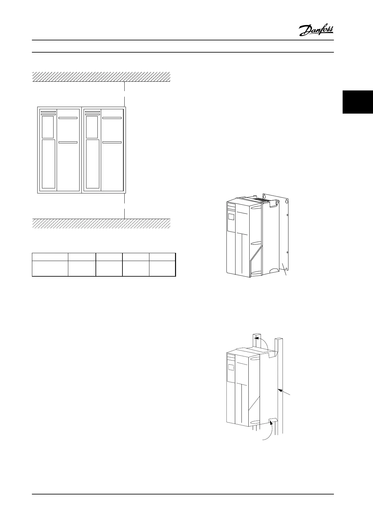
Figure 2.1 Top and Bottom Cooling Clearance
Enclosure A2-A5 B1-B4 C1, C3 C2, C4
a/b (inch
[mm])
100 200 200 225
Table 2.1 Minimum Airflow Clearance Requirements
2.3.2
Lifting
•
Check the weight of the unit to determine a safe
lifting method
•
Ensure that the lifting device is suitable for the
task
•
If necessary, plan for a hoist, crane, or forklift with
the appropriate rating to move the unit
•
For lifting, use hoist rings on the unit, where
provided
2.3.3
Mounting
•
Mount the unit vertically.
•
The adjustable frequency drive allows side by
side installation.
•
Ensure that the strength of the mounting location
will support the unit weight.
•
Mount the unit onto a solid flat surface or onto
the optional backplate to provide cooling airflow
(see Figure 2.2 and Figure 2.3).
•
Improper mounting can result in overheating and
reduced performance.
•
Use the slotted mounting holes on the unit for
wall mounting, when provided.
Figure 2.2 Proper Mounting with Backplate
Item A in Figure 2.2 and Figure 2.3 is a backplate properly
installed for required airflow to cool the unit.
Figure 2.3 Proper Mounting with Railings
Installation Instruction Manual
MG16E222 Danfoss A/S © Rev. 2014-02-10 All rights reserved. 9
2 2

 Loading...


