91
L1
92
L2
93
L3
96
U
97
V
98
W
88
DC-
89
DC+
81
R-
8
R+
130BA390.11
99
95
Figure 2.12 Motor, Line Power and Ground Wiring for Frame
Sizes B, C and D Using Shielded Cable
130BB477.10
91
L1
92
L2
93
L3
96
U
97
V
99
W
88
DC+
89
DC-
91
R-
9
R+
95
99
Figure 2.13 Motor, Line Power and Ground Wiring for Frame
Sizes B, C and D Using Conduit
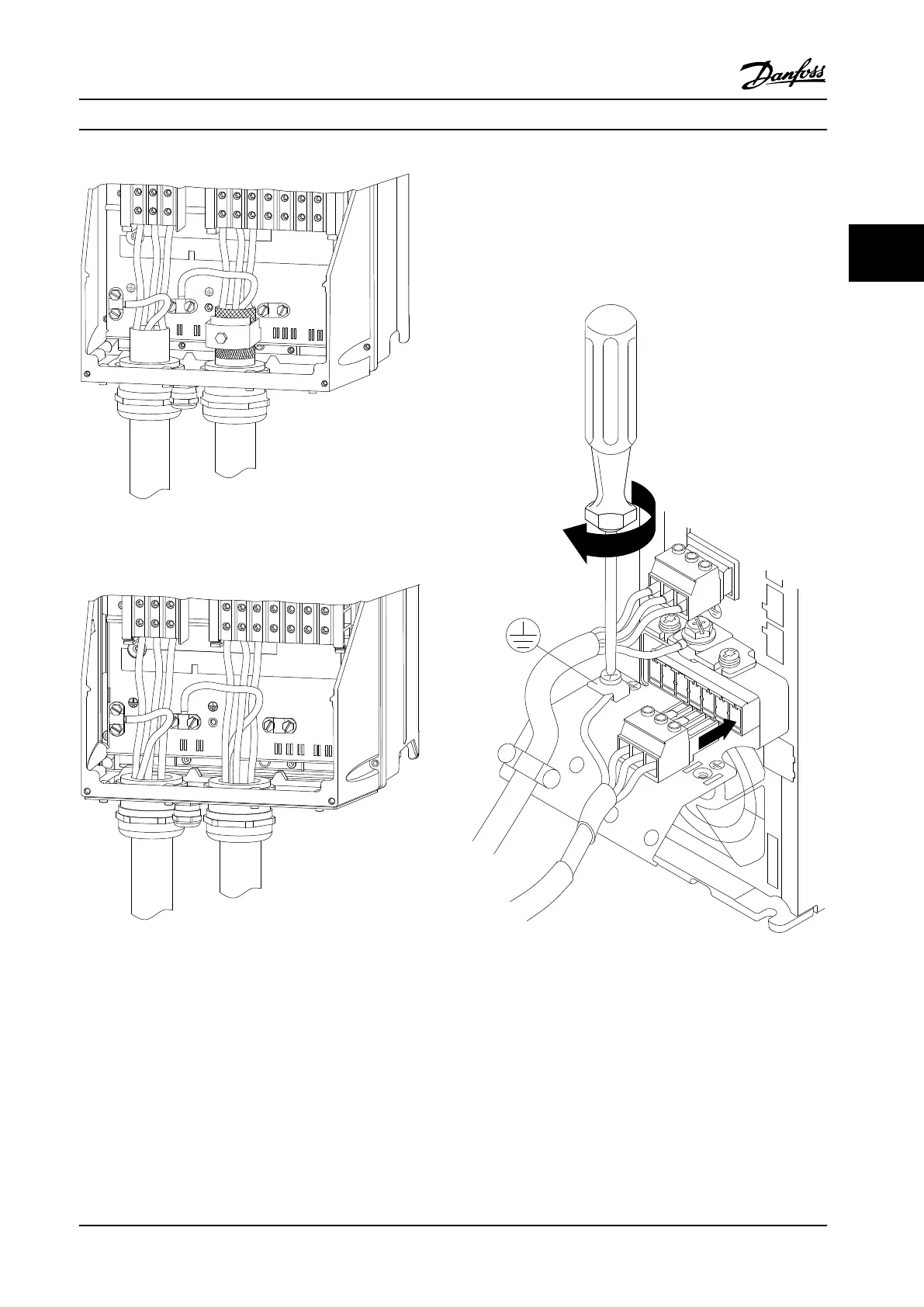
2.4.4.1
Motor Connection for A2 and A3
Follow these drawings step-by-step for connecting the
motor to the adjustable frequency drive.
1. Terminate the motor ground, place motor U, V
and W wires in plug and tighten.
MAINS
L1 L2 L3
91 92 93
- LC +
RELAY 1 RELAY 2
+DC
BR-
B
+DC BR- BR+ U V W
99
UVW
MOTOR
130BA265.10
Figure 2.14 Motor Connection for A2 and A3
Installation Instruction Manual
MG16E222 Danfoss A/S © Rev. 2014-02-10 All rights reserved. 17
2 2
 Loading...


