2.4.1 Requirements
WARNING
EQUIPMENT HAZARD!
Rotating shafts and electrical equipment can be
hazardous. All electrical work must conform to national
and local electrical codes. It is strongly recommended
that installation, start-up, and maintenance be
performed only by trained and qualified personnel.
Failure to follow these guidelines could result in death or
serious injury.
CAUTION
WIRING ISOLATION!
Run input power, motor wiring and control wiring in
three separate metallic conduits or use separated
shielded cable for high frequency noise isolation. Failure
to isolate power, motor and control wiring could result
in less than optimum adjustable frequency drive and
associated equipment performance.
For your safety, comply with the following requirements.
•
Electronic controls equipment is connected to
hazardous AC line voltage. Extreme care should
be taken to protect against electrical hazards
when applying power to the unit.
•
Run motor cables from multiple adjustable
frequency drives separately. Induced voltage from
output motor cables run together can charge
equipment capacitors even with the equipment
turned off and locked out.
Overload and Equipment Protection
•
An electronically activated function within the
adjustable frequency drive provides overload
protection for the motor. The overload calculates
the level of increase to activate timing for the trip
(controller output stop) function. The higher the
current draw, the quicker the trip response. The
overload provides Class 20 motor protection. See
chapter 8 Warnings and Alarms for details on the
trip function.
•
Because the motor wiring carries high frequency
current, it is important that wiring for line power,
motor power, and control is run separately. Use
metallic conduit or separated shielded wire.
Failure to isolate power, motor, and control
wiring could result in less than optimum
equipment performance. See Figure 2.6.
Stop
Start
Speed
Control
Line
Power
Separate Conduit
Motor
130BB447.10
Figure 2.6 Proper Electrical Installation Using Conduit
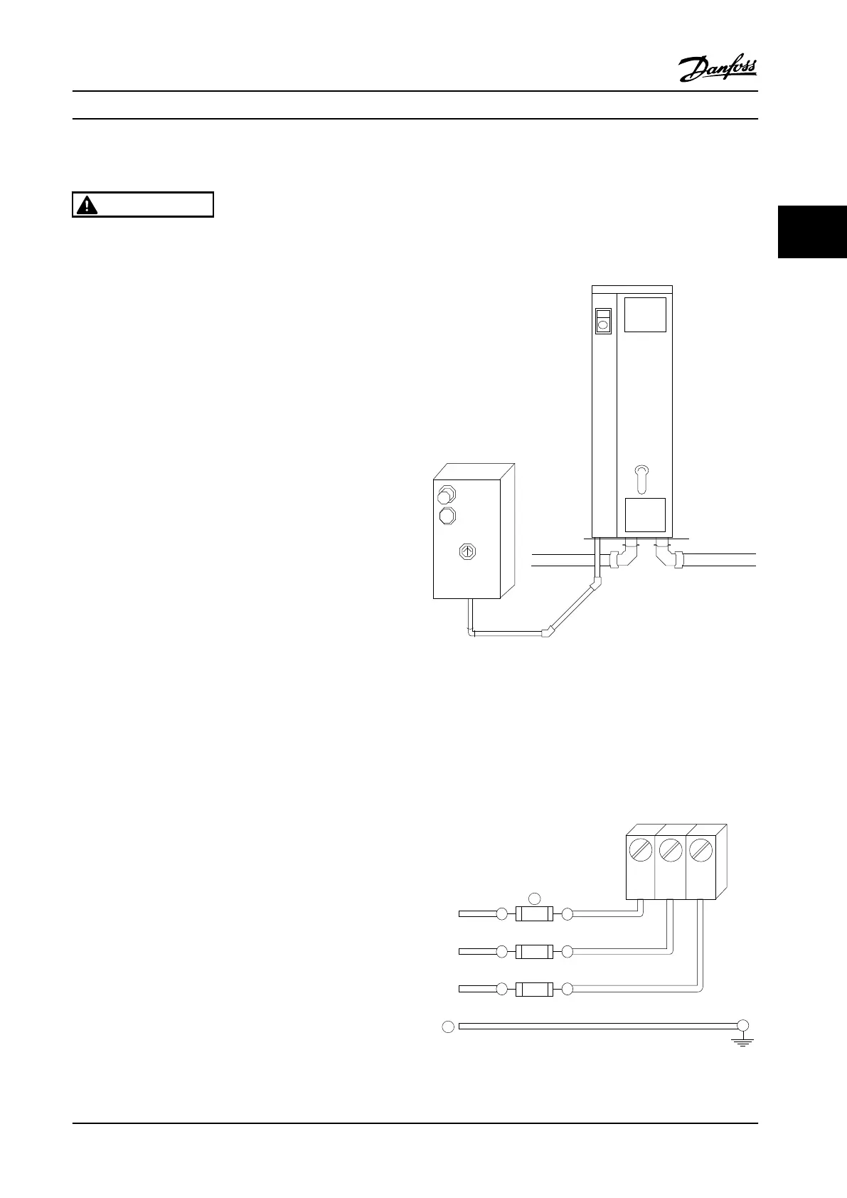
•
All adjustable frequency drives must be provided
with short-circuit and overcurrent protection.
Input fusing is required to provide this
protection, see Figure 2.7. If not factory supplied,
fuses must be provided by the installer as part of
installationinstallation. See maximum fuse ratings
in chapter 10.1 Power-dependent Specifications.
L1
L1
L2
L2
L3
L3
2
91 92 93
1
130BB460.11
Figure 2.7 Adjustable Frequency Drive Fuses
Installation Instruction Manual
MG16E222 Danfoss A/S © Rev. 2014-02-10 All rights reserved. 13
2 2
 Loading...


