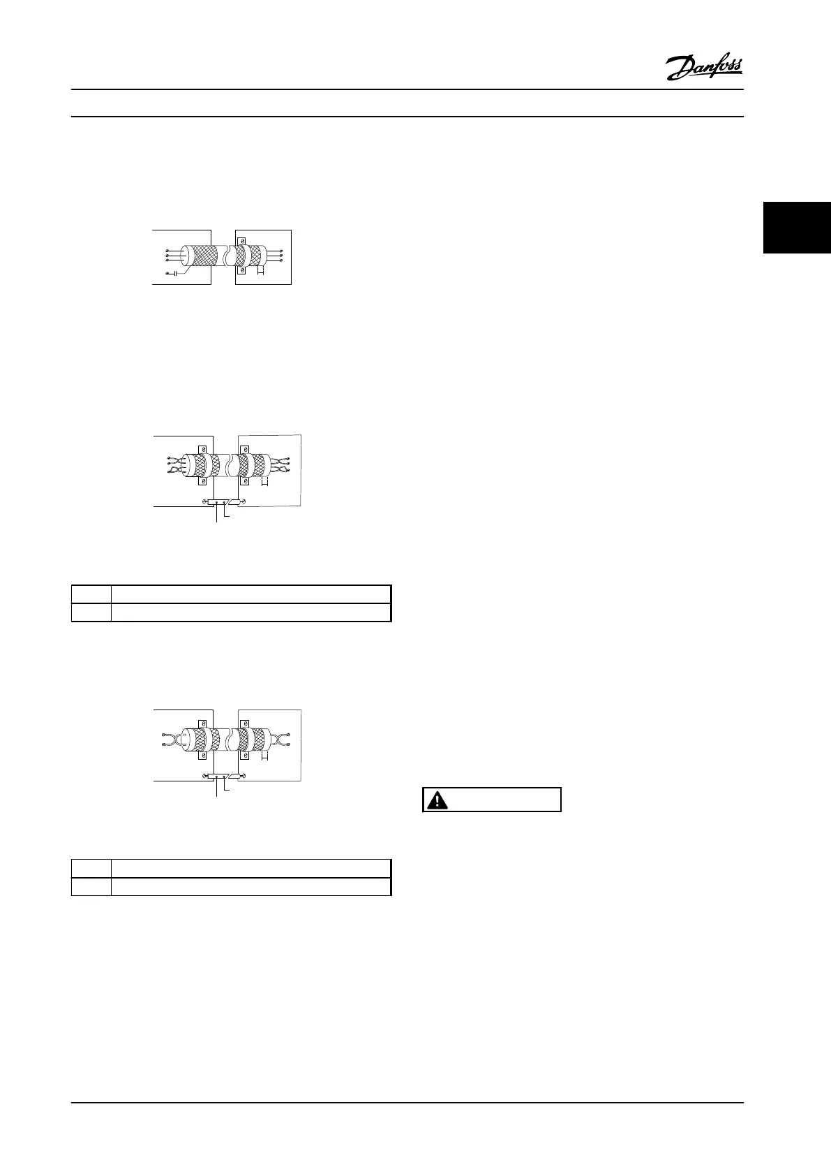
50/60 Hz ground loops
With very long control cables, ground loops may occur. To
eliminate ground loops, connect one end of the shield-to-
ground with a 100 nF capacitor (keeping leads short).
100nF
FC
PE
PE
PLC
<10 mm
130BB609.12
Figure 2.32 50/60 Hz Ground Loops
Avoid EMC noise on serial communication
This terminal is grounded via an internal RC link. Use
twisted-pair cables to reduce interference between
conductors. The recommended method is shown in
Figure 2.33:
PE
FC
PE
FC
130BB923.12
PE PE
69
68
61
69
68
61
1
2
<10 mm
Figure 2.33 Twisted-pair Cables
1
Min. 0.025 in
2
[16 mm
2
]
2 Equalizing cable
Table 2.7 Legend to Figure 2.33
Alternatively, the connection to terminal 61 can be
omitted:
PE
FC
PE
FC
130BB924.12
PE PE
69
69
68
68
1
2
<10 mm
Figure 2.34 Twisted-pair Cables without Terminal 61
1
Min. 0.025 in
2
[16 mm
2
]
2 Equalizing cable
Table 2.8 Legend to Figure 2.34
2.4.6.4
Jumper Terminals 12 and 27
A jumper wire may be required between terminal 12 (or
13) and terminal 27 for the adjustable frequency drive to
operate when using factory default programming values.
•
Digital input terminal 27 is designed to receive a
24 V DC external interlock command. In many
applications, the user wires an external interlock
device to terminal 27.
•
When no interlock device is used, wire a jumper
between control terminal 12 (recommended) or
13 to terminal 27. This provides an internal 24 V
signal on terminal 27.
•
No signal present prevents the unit from
operating.
•
When the status line at the bottom of the LCP
reads AUTO REMOTE COASTING or Alarm 60
External Interlock is displayed, this indicates that
the unit is ready to operate but is missing an
input signal on terminal 27.
•
When factory installed optional equipment is
wired to terminal 27, do not remove that wiring.
2.4.6.5
Terminal 53 and 54 Switches
•
Analog input terminals 53 and 54 can select
either voltage (0 to 10 V) or current (0/4–20 mA)
input signals.
•
Remove power to the adjustable frequency drive
before changing switch positions.
•
Set switches A53 and A54 to select the signal
type. U selects voltage, I selects current.
•
The switches are accessible when the LCP has
been removed (see Figure 2.35).
WARNING
Some option cards available for the unit may cover these
switches and must be removed to change switch
settings. Always remove power to the unit before
removing option cards.
•
Terminal 53 default is for a speed reference signal
in open-loop set in 16-61 Terminal 53 Switch
Setting
•
Terminal 54 default is for a feedback signal in
closed-loop set in 16-63 Terminal 54 Switch Setting
Installation
Instruction Manual
MG16E222 Danfoss A/S © Rev. 2014-02-10 All rights reserved. 25
2 2

 Loading...


