Figure 2.10 Control Wiring Access for A4, A5, B1,
B2, C1 and C2 Enclosures
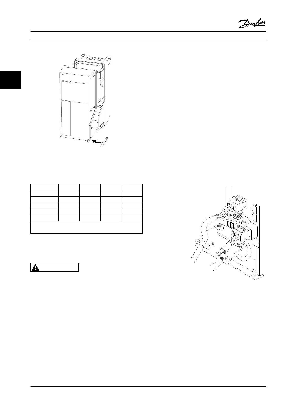
See Table 2.3 before tightening the covers.
Frame IP20 IP21 IP55 IP66
A4/A5 - - 2 2
B1 - * 2.2 2.2
B2 - * 2.2 2.2
C1 - * 2.2 2.2
C2 - * 2.2 2.2
* No screws to tighten
- Does not exist
Table 2.3 Tightening Torques for Covers (Nm)
2.4.4
Motor Connection
WARNING
INDUCED VOLTAGE!
Run output motor cables from multiple adjustable
frequency drives separately. Induced voltage from
output motor cables run together can charge equipment
capacitors even with the equipment turned off and
locked out. Failure to run output motor cables separately
could result in death or serious injury.
•
For maximum wire sizes, see chapter 10.1 Power-
dependent Specifications
•
Comply with local and national electrical codes
for cable sizes
•
Motor wiring knockouts or access panels are
provided at the base of IP21 and higher
(NEMA1/12) units
•
Do not install power factor correction capacitors
between the adjustable frequency drive and the
motor
•
Do not wire a starting or pole-changing device
between the adjustable frequency drive and the
motor
•
Connect the 3-phase motor wiring to terminals
96 (U), 97 (V), and 98 (W)
•
Ground the cable in accordance with grounding
instructions provided
•
Torque terminals in accordance with the
information provided in chapter 10.4 Connection
Tightening Torques
•
Follow the motor manufacturer wiring
requirements
Figure 2.11, Figure 2.12 and Figure 2.13 represent line power
input, motor, and grounding for basic adjustable frequency
drives. Actual configurations vary with unit types and
optional equipment.
130BA266.10
+DC
BR-
B
MAINS
L1 L2 L3
91 92 93
RELAY 1 RELAY 2
99
- LC -
UVW
MOTOR
Figure 2.11 Motor, Line Power and Ground Wiring for Frame
Size A
Installation Instruction Manual
16 Danfoss A/S © Rev. 2014-02-10 All rights reserved. MG16E222
22
 Loading...


