EasyManuals Logo

Danfoss VLT HVAC Design Guide

Danfoss VLT HVAC
200 pages
To Next Page IconTo Next Page
To Previous Page IconTo Previous Page
Page #104 background imageLoading...
Page #104 background image
1. Use a clamp from the accessory bag to connect the screen to
the frequency converter decoupling plate for control cables.
See section entitled
Earthing of Screened/Armoured Control Cables
for
the correct termination of control cables.
130BA681.10
130BA681.10
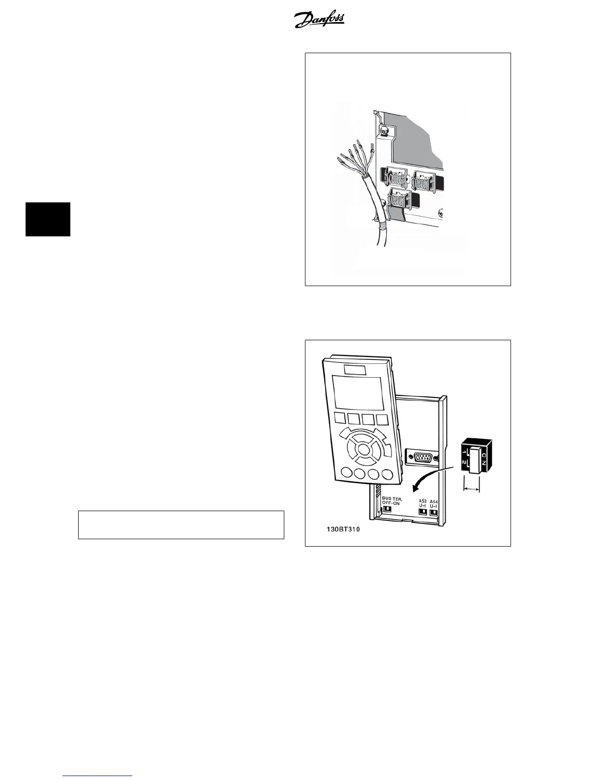
5.2.13 Switches S201, S202, and S801
Switches S201 (A53) and S202 (A54) are used to select a current (0-20
mA) or a voltage (0 to 10 V) configuration of the analog input terminals
53 and 54 respectively.
Switch S801 (BUS TER.) can be used to enable termination on the RS-485
port (terminals 68 and 69).
See drawing
Diagram showing all electrical terminals
in section
Electrical
Installation.
Default setting:
S201 (A53) = OFF (voltage input)
S202 (A54) = OFF (voltage input)
S801 (Bus termination) = OFF
NB!
It is recommended to only change switch position at power off.
5 How to Install VLT
®
HVAC Drive Design Guide
104
MG.11.B9.02 - VLT
®
is a registered Danfoss trademark
5

Table of Contents

Other manuals for Danfoss VLT HVAC

Questions and Answers:

Question and Answer IconNeed help?

Do you have a question about the Danfoss VLT HVAC and is the answer not in the manual?

Danfoss VLT HVAC Specifications

General IconGeneral
Enclosure RatingIP20, IP21, IP54, IP55, IP66
Storage Temperature Range-25°C to +70°C
Output Voltage Range0-100% of supply voltage
Communication ProtocolsModbus RTU, BACnet, Ethernet/IP, Profibus DP
Ambient Temperature Range-10°C to +50°C (without derating)
Relative Humidity5% to 95% non-condensing
AltitudeUp to 1000 m without derating
Cooling MethodAir cooled
ApplicationHVAC systems, Pumps, Fans, Compressors
Voltage Range200-240 V, 380-500 V, 525-600 V
Frequency Range0 Hz to 590 Hz

Related product manuals