EasyManuals Logo

Danfoss VLT HVAC Design Guide

Danfoss VLT HVAC
200 pages
To Next Page IconTo Next Page
To Previous Page IconTo Previous Page
Page #103 background imageLoading...
Page #103 background image
5.2.12 Electrical Installation, Control Cables
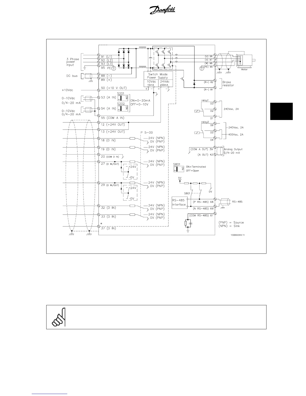
Illustration 5.20: Diagram showing all electrical terminals. (Terminal 37 present for units with Safe Stop Function only.)
Very long control cables and analog signals may in rare cases and depending on installation result in 50/60 Hz earth loops due to noise from mains supply
cables.
If this occurs, you may have to break the screen or insert a 100 nF capacitor between screen and chassis.
The digital and analog in- and outputs must be connected separately to the frequency converter common inputs (terminal 20, 55, 39) to avoid ground
currents from both groups to affect other groups. For example, switching on the digital input may disturb the analog input signal.
NB!
Control cables must be screened/armoured.
VLT
®
HVAC Drive Design Guide 5 How to Install
MG.11.B9.02 - VLT
®
is a registered Danfoss trademark
103
5

Table of Contents

Other manuals for Danfoss VLT HVAC

Questions and Answers:

Question and Answer IconNeed help?

Do you have a question about the Danfoss VLT HVAC and is the answer not in the manual?

Danfoss VLT HVAC Specifications

General IconGeneral
Enclosure RatingIP20, IP21, IP54, IP55, IP66
Storage Temperature Range-25°C to +70°C
Output Voltage Range0-100% of supply voltage
Communication ProtocolsModbus RTU, BACnet, Ethernet/IP, Profibus DP
Ambient Temperature Range-10°C to +50°C (without derating)
Relative Humidity5% to 95% non-condensing
AltitudeUp to 1000 m without derating
Cooling MethodAir cooled
ApplicationHVAC systems, Pumps, Fans, Compressors
Voltage Range200-240 V, 380-500 V, 525-600 V
Frequency Range0 Hz to 590 Hz

Related product manuals