2.8.3 Local (Hand On) and Remote (Auto On) Control
The frequency converter can be operated manually via the local control panel (LCP) or remotely via analog/digital inputs or serial bus.
If allowed in par. 0-40
[Hand on] Key on LCP
, par. 0-41
[Off] Key on LCP
, par. 0-42
[Auto on] Key on LCP
, and par. 0-43
[Reset] Key on LCP
, it is possible
to start and stop the frequency converter byLCP using the [Hand ON] and [Off] keys. Alarms can be reset via the [RESET] key. After pressing the [Hand
ON] key, the frequency converter goes into Hand Mode and follows (as default) the Local reference set by using the LCP arrow keys up [
▲
] and down
[
▼
].
After pressing the [Auto On] key, the frequency converter goes into Auto
mode and follows (as default) the Remote reference. In this mode, it is
possible to control the frequency converter via the digital inputs and var-
ious serial interfaces (RS-485, USB, or an optional fieldbus). See more
about starting, stopping, changing ramps and parameter set-ups etc. in
par. group 5-1* (digital inputs) or par. group 8-5* (serial communica-
tion).
130BP046.10
Hand Off
Auto
LCP Keys
Reference Site
par. 3-13
Reference Site
Active Reference
Hand Linked to Hand / Auto Local
Hand -> Off Linked to Hand / Auto Local
Auto Linked to Hand / Auto Remote
Auto -> Off Linked to Hand / Auto Remote
All keys Local Local
All keys Remote Remote
The table shows under which conditions either the Local Reference or the Remote Reference is active. One of them is always active, but both can not be
active at the same time.
Local reference will force the configuration mode to open loop, independent on the setting of par. 1-00
Configuration Mode
.
Local Reference will be restored at power-down.
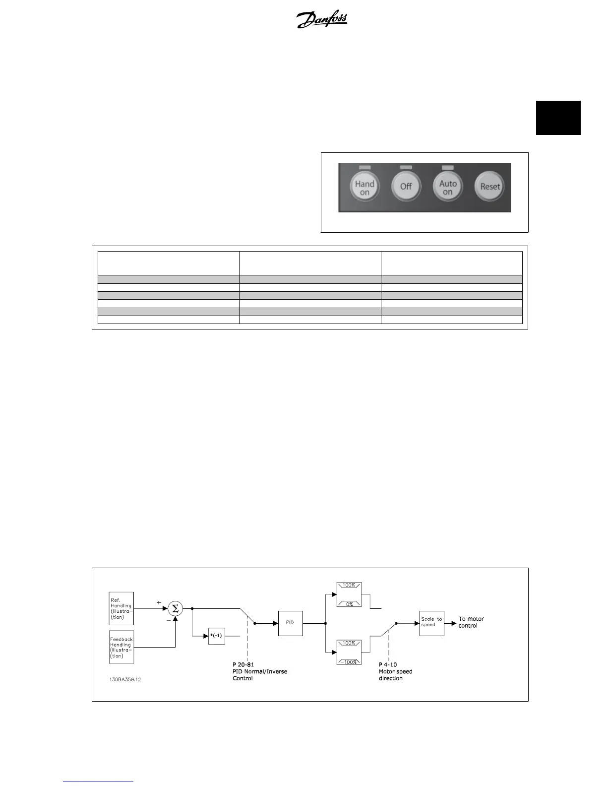
2.8.4 Control Structure Closed Loop
The internal controller allows the drive to become an integral part of the controlled system. The drive receives a feedback signal from a sensor in the
system. It then compares this feedback to a set-point reference value and determines the error, if any, between these two signals. It then adjusts the
speed of the motor to correct this error.
For example, consider a pump application where the speed of a pump is to be controlled so that the static pressure in a pipe is constant. The desired
static pressure value is supplied to the drive as the set-point reference. A static pressure sensor measures the actual static pressure in the pipe and
supplies this to the drive as a feedback signal. If the feedback signal is greater than the set-point reference, the drive will slow down to reduce the
pressure. In a similar way, if the pipe pressure is lower than the set-point reference, the drive will automatically speed up to increase the pressure provided
by the pump.
VLT
®
HVAC Drive Design Guide 2 Introduction to VLT HVAC Drive
MG.11.B9.02 - VLT
®
is a registered Danfoss trademark
33
2

 Loading...


