While the default values for the drive’s Closed Loop controller will often provide satisfactory performance, the control of the system can often be optimized
by adjusting some of the Closed Loop controller’s parameters. It is also possible to autotune the PI constants.
The figure is a block diagram of the drive’s Closed Loop controller. The details of the Reference Handling block and Feedback Handling block are described
in their respective sections below.
2.8.5 Feedback Handling
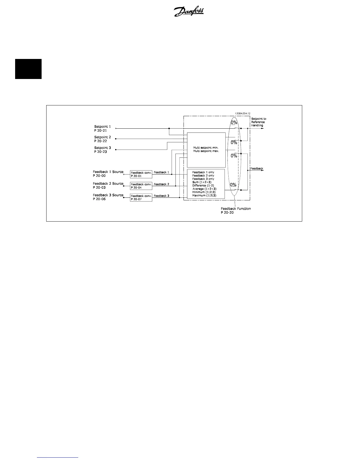
A block diagram of how the drive processes the feedback signal is shown below.
Feedback handling can be configured to work with applications requiring advanced control, such as multiple setpoints and multiple feedbacks. Three
types of control are common.
Single Zone, Single Setpoint
Single Zone Single Setpoint is a basic configuration. Setpoint 1 is added to any other reference (if any, see Reference Handling) and the feedback signal
is selected using par. 20-20
Feedback Function
.
Multi Zone, Single Setpoint
Multi Zone Single Setpoint uses two or three feedback sensors but only one setpoint. The feedbacks can be added, subtracted (only feedback 1 and 2)
or averaged. In addition, the maximum or minimum value may be used. Setpoint 1 is used exclusively in this configuration.
If
Multi Setpoint Min
[13] is selected, the setpoint/feedback pair with the largest difference controls the speed of the drive.
Multi Setpoint Maximum
[14]
attempts to keep all zones at or below their respective setpoints, while
Multi Setpoint Min
[13] attempts to keep all zones at or above their respective
setpoints.
Example:
A two zone two setpoint application Zone 1 setpoint is 15 bar and the feedback is 5.5 bar. Zone 2 setpoint is 4.4 bar and the feedback is 4.6 bar. If
Multi
Setpoint Max
[14] is selected, Zone 1’s setpoint and feedback are sent to the PID controller, since this has the smaller difference (feedback is higher than
setpoint, resulting in a negative difference). If
Multi Setpoint Min
[13] is selected, Zone 2’s setpoint and feedback is sent to the PID controller, since this
has the larger difference (feedback is lower than setpoint, resulting in a positive difference).
2 Introduction to VLT HVAC Drive VLT
®
HVAC Drive Design Guide
34
MG.11.B9.02 - VLT
®
is a registered Danfoss trademark
2

 Loading...


