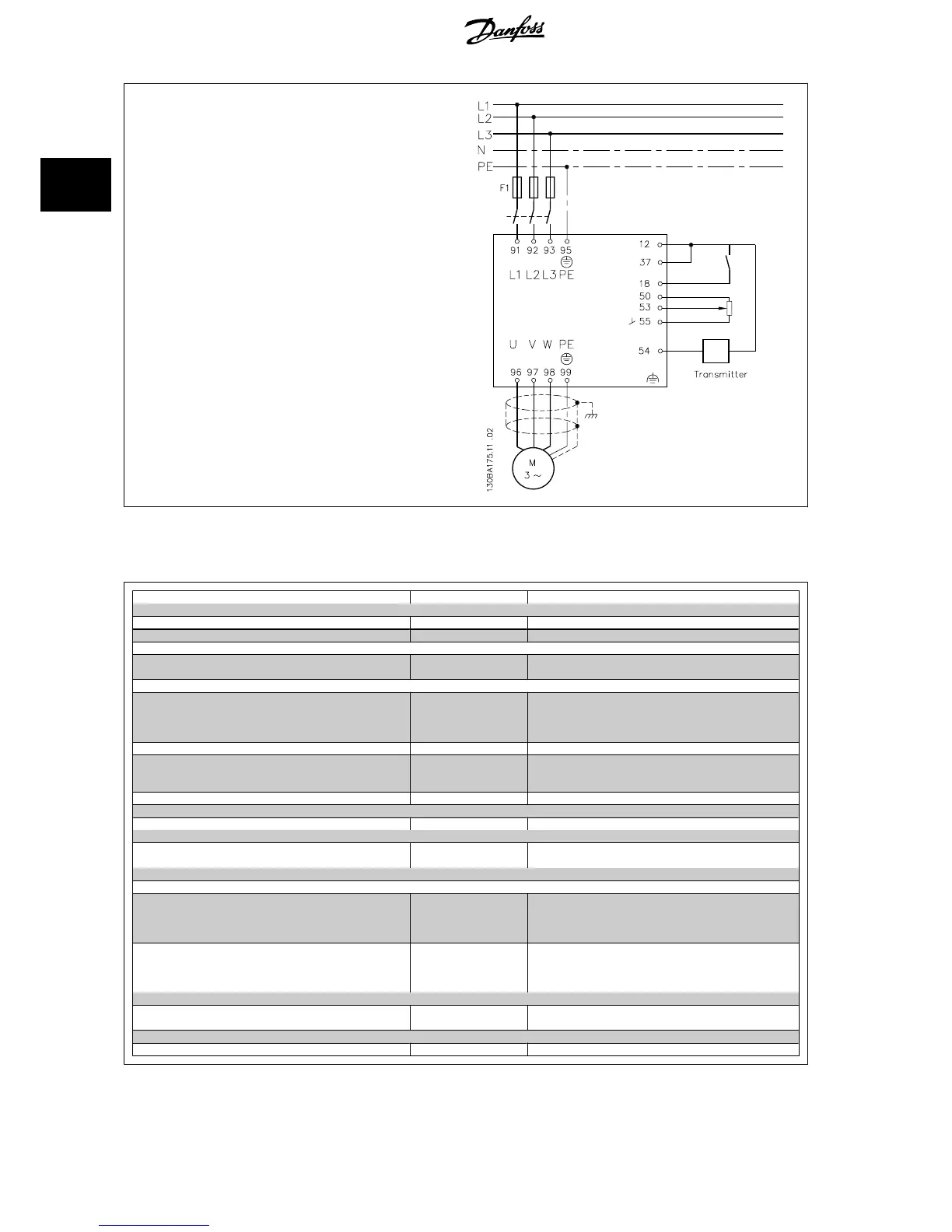
1. Start/Stop via switch connected between terminals 12 (+24 V) and 18.
2. Temperature reference via a potentiometer (-5 to +35°C, 0 10 V)
connected to terminals 50 (+10 V), 53 (input) and 55 (common).
3. Temperature feedback via transmitter (-10-40°C, 4-20 mA) connected
to terminal 54. Switch S202 behind the LCP set to ON (current input).
2.8.9 Programming Order
Function Par. no. Setting
1) Make sure the motor runs properly. Do the following:
Set the motor parameters using nameplate data.
1-2* As specified by motor name plate
Run Automatic Motor Adaptation. 1-29
Enable complete AMA
[1] and then run the AMA function.
2) Check that the motor is running in the right direction.
Run Motor Rotation Check. 1-28 If the motor runs in the wrong direction, remove power
temporarily and reverse two of the motor phases.
3) Make sure the frequency converter limits are set to safe values
Check that the ramp settings are within capabilities of the
drive and allowed application operating specifications.
3-41
3-42
60 sec.
60 sec.
Depends on motor/load size!
Also active in Hand mode.
Prohibit the motor from reversing (if necessary) 4-10
Clockwise
[0]
Set acceptable limits for the motor speed. 4-12
4-14
4-19
10 Hz,
Motor min speed
50 Hz,
Motor max speed
50 Hz,
Drive max output frequency
Switch from open loop to closed loop. 1-00
Closed Loop
[3]
4) Configure the feedback to the PID controller.
Select the appropriate reference/feedback unit.
20-12
Bar
[71]
5) Configure the set-point reference for the PID controller.
Set acceptable limits for the set-point reference.
20-13
20-14
0 Bar
10 Bar
Choose current or voltage by switches S201 / S202
6) Scale the analog inputs used for set-point reference and feedback.
Scale Analog Input 53 for the pressure range of the potenti-
ometer (0 - 10 Bar, 0 - 10 V).
6-10
6-11
6-14
6-15
0 V
10 V (default)
0 Bar
10 Bar
Scale Analog Input 54 for pressure sensor (0 - 10 Bar, 4 - 20
mA)
6-22
6-23
6-24
6-25
4 mA
20 mA (default)
0 Bar
10 Bar
7) Tune the PID controller parameters.
Adjust the drive’s Closed Loop Controller, if needed.
20-93
20-94
See Optimization of the PID Controller, below.
8) Finished!
Save the parameter setting to the LCP for safe keeping
0-50
All to LCP
[1]
2 Introduction to VLT HVAC Drive VLT
®
HVAC Drive Design Guide
38
MG.11.B9.02 - VLT
®
is a registered Danfoss trademark
2

 Loading...


