The Remote Reference is comprised of:
• Preset references.
• External references (analog inputs, pulse frequency inputs, digital potentiometer inputs and serial communication bus references).
• The Preset relative reference.
•Feedback controlled setpoint.
Up to 8 preset references can be programmed in the drive. The active preset reference can be selected using digital inputs or the serial communications
bus. The reference can also be supplied externally, most commonly from an analog input. This external source is selected by one of the 3 Reference
Source parameters (par. 3-15
Reference 1 Source
, par. 3-16
Reference 2 Source
and par. 3-17
Reference 3 Source
). Digipot is a digital potentiometer.
This is also commonly called a Speed Up/Speed Down Control or a Floating Point Control. To set it up, one digital input is programmed to increase the
reference while another digital input is programmed to decrease the reference. A third digital input can be used to reset the Digipot reference. All reference
resources and the bus reference are added to produce the total External Reference. The External Reference, the Preset Reference or the sum of the two
can be selected to be the active reference. Finally, this reference can by be scaled using par. 3-14
Preset Relative Reference
.
The scaled reference is calculated as follows:
Reference
=
X
+
X
×
(
Y
100
)
Where X is the external reference, the preset reference or the sum of these and Y is par. 3-14
Preset Relative Reference
in [%].
If Y, par. 3-14
Preset Relative Reference
is set to 0%, the reference will not be affected by the scaling.
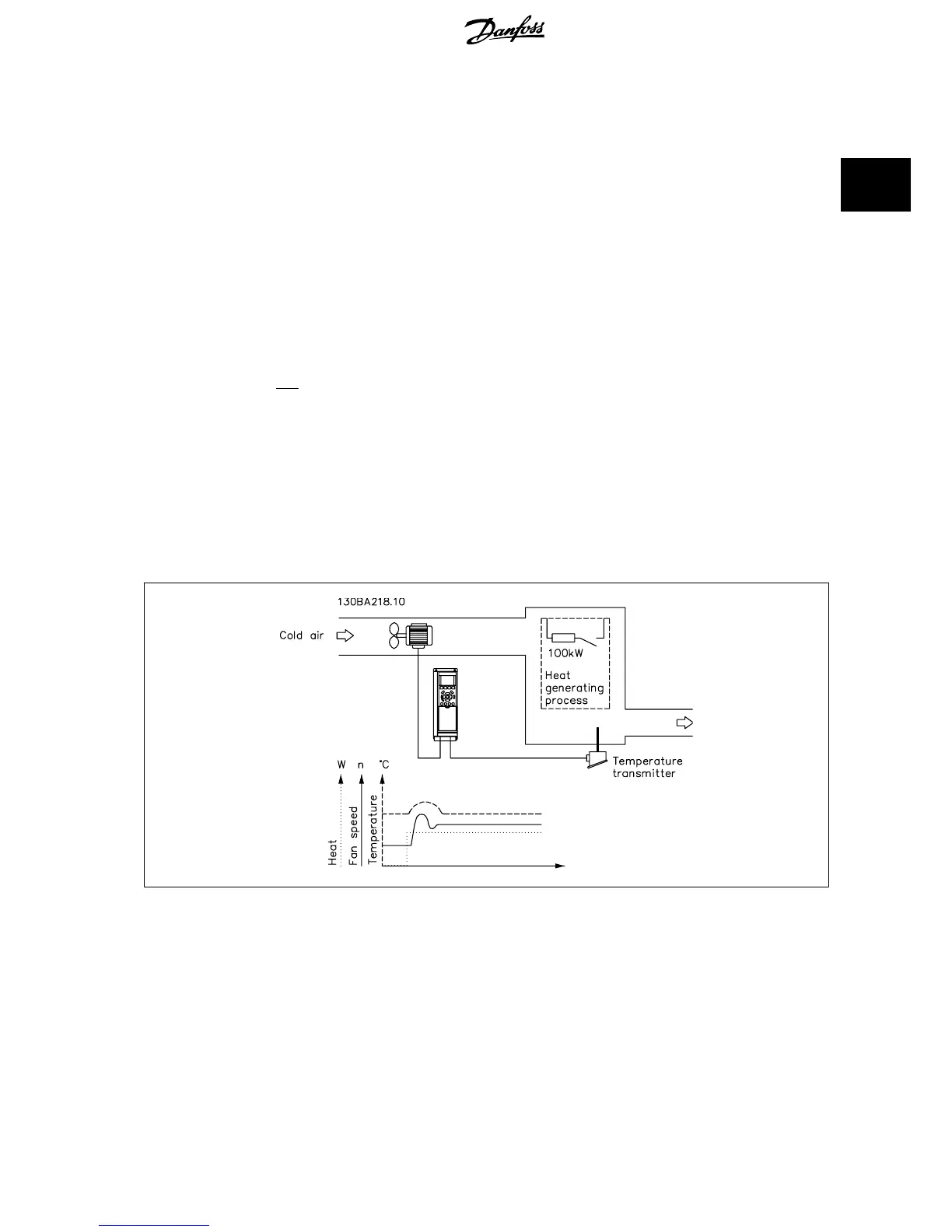
2.8.8 Example of Closed Loop PID Control
The following is an example of a Closed Loop Control for a ventilation system:
In a ventilation system, the temperature is to be maintained at a constant value. The desired temperature is set between -5 and +35°C using a 0-10 volt
potentiometer. Because this is a cooling application, if the temperature is above the set-point value, the speed of the fan must be increased to provide
more cooling air flow. The temperature sensor has a range of -10 to +40°C and uses a two-wire transmitter to provide a 4-20 mA signal. The output
frequency range of the frequency converter is 10 to 50 Hz.
VLT
®
HVAC Drive Design Guide 2 Introduction to VLT HVAC Drive
MG.11.B9.02 - VLT
®
is a registered Danfoss trademark
37
2

 Loading...


