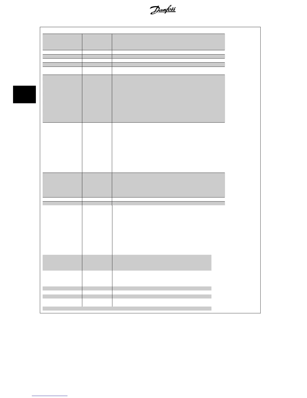
Ordering type code frame size F
Description Pos Possible choice
Product group 1-3
Drive series 4-6
Power rating 8-10 500 - 1400 kW
Phases 11 Three phases (T)
Mains voltage 11-
12
T 5: 380-500 VAC
T 7: 525-690 VAC
Enclosure 13-
15
E21: IP 21/ NEMA Type 1
E54: IP 54/ NEMA Type 12
L2X: IP21/NEMA 1 with cabinet light & IEC 230V power outlet
L5X: IP54/NEMA 12 with cabinet light & IEC 230V power outlet
L2A: IP21/NEMA 1 with cabinet light & NAM 115V power outlet
L5A: IP54/NEMA 12 with cabinet light & NAM 115V power outlet
H21: IP21 with space heater and thermostat
H54: IP54 with space heater and thermostat
R2X: IP21/NEMA1 with space heater, thermostat, light & IEC 230V outlet
R5X: IP54/NEMA12 with space heater, thermostat, light & IEC 230V outlet
R2A: IP21/NEMA1 with space heater, thermostat, light, & NAM 115V outlet
R5A: IP54/NEMA12 with space heater, thermostat, light, & NAM 115V outlet
RFI filter 16-
17
H2: RFI filter, class A2 (standard)
H4: RFI filter, class A1
2, 3)
HE: RCD with Class A2 RFI filter
2)
HF: RCD with class A1 RFI filter
2, 3)
HG: IRM with Class A2 RFI filter
2)
HH: IRM with class A1 RFI filter
2, 3)
HJ: NAMUR terminals and class A2 RFI filter
1)
HK: NAMUR terminals with class A1 RFI filter
1, 2, 3)
HL: RCD with NAMUR terminals and class A2 RFI filter
1, 2)
HM: RCD with NAMUR terminals and class A1 RFI filter
1, 2, 3)
HN: IRM with NAMUR terminals and class A2 RFI filter
1, 2)
HP: IRM with NAMUR terminals and class A1 RFI filter
1, 2, 3)
Brake 18 B: Brake IGBT mounted
X: No brake IGBT
R: Regeneration terminals
M: IEC Emergency stop push-button (with Pilz safety relay)
4)
N: IEC Emergency stop push-button with brake IGBT and brake terminals
4)
P: IEC Emergency stop push-button with regeneration terminals
4)
Display 19 G: Graphical Local Control Panel LCP
Coating PCB 20 C: Coated PCB
Mains option 21 X: No mains option
3
2)
: Mains disconnect and Fuse
5
2)
: Mains disconnect, Fuse and Load sharing
7: Fuse
A: Fuse and Load sharing
D: Load sharing
E: Mains disconnect, contactor & fuses
2)
F: Mains circuit breaker, contactor & fuses
2)
G: Mains disconnect, contactor, loadsharing terminals & fuses
2)
H: Mains circuit breaker, contactor, loadsharing terminals & fuses
2)
J: Mains circuit breaker & fuses
2)
K: Mains circuit breaker, loadsharing terminals & fuses
2)
A options 29-30 AX: No options
A0: MCA 101 Profibus DP V1
A4: MCA 104 DeviceNet
AN: MCA 121 Ethernet IP
B options 31-32 BX: No option
BK: MCB 101 General purpose I/O option
BP: MCB 105 Relay option
BO: MCB 109 Analog I/O option
C
0
options 33-34 CX: No options
C
1
options 35 X: No options
C option software 36-37 XX: Standard software
D options 38-39 DX: No option
D0: DC backup
The various options are described further in this Design Guide.
4 How to Order VLT
®
HVAC Drive Design Guide
68
MG.11.B9.02 - VLT
®
is a registered Danfoss trademark
4

 Loading...


