5.1.4 Mechanical mounting
All A, B and C enclosures allow side-by-side installation.
Exception: If a IP21 kit is used, there has to be a clearance between the enclosures. For enclosures A2, A3, B3,B4 and C3 the minimum clearance is 50
mm, for C4 it is 75 mm.
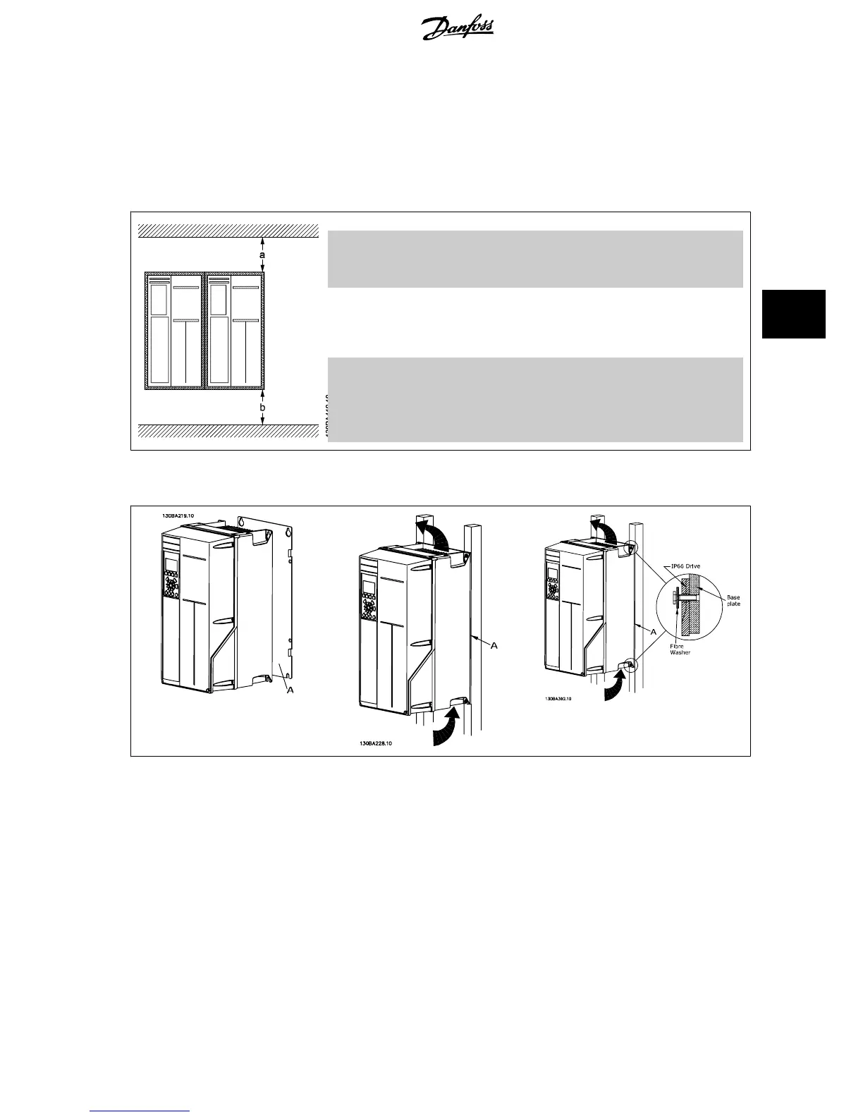
For optimal cooling conditions allow a free air passage above and below the frequency converter. See table below.
Air passage for different enclosures
Enclo-
sure:
A2 A3 A5 B1 B2 B3 B4 C1 C2 C3 C4
a (mm): 100 100 100 200 200 200 200 200 225 200 225
b (mm): 100 100 100 200 200 200 200 200 225 200 225
1. Drill holes in accordance with the measurements given.
2. You must provide screws suitable for the surface on which you want to mount the frequency converter. Retighten all four screws.
Table 5.1: When mounting enclosure sizes A5, B1, B2, B3, B4, C1, C2, C3 and C4 on a non-solid back wall, the drive must be provided with a back plate
A due to insufficient cooling air over the heat sink.
VLT
®
HVAC Drive Design Guide 5 How to Install
MG.11.B9.02 - VLT
®
is a registered Danfoss trademark
85
5

 Loading...


