EasyManuals Logo

Danfoss VLT HVAC Design Guide

Danfoss VLT HVAC
200 pages
To Next Page IconTo Next Page
To Previous Page IconTo Previous Page
Page #84 background imageLoading...
Page #84 background image
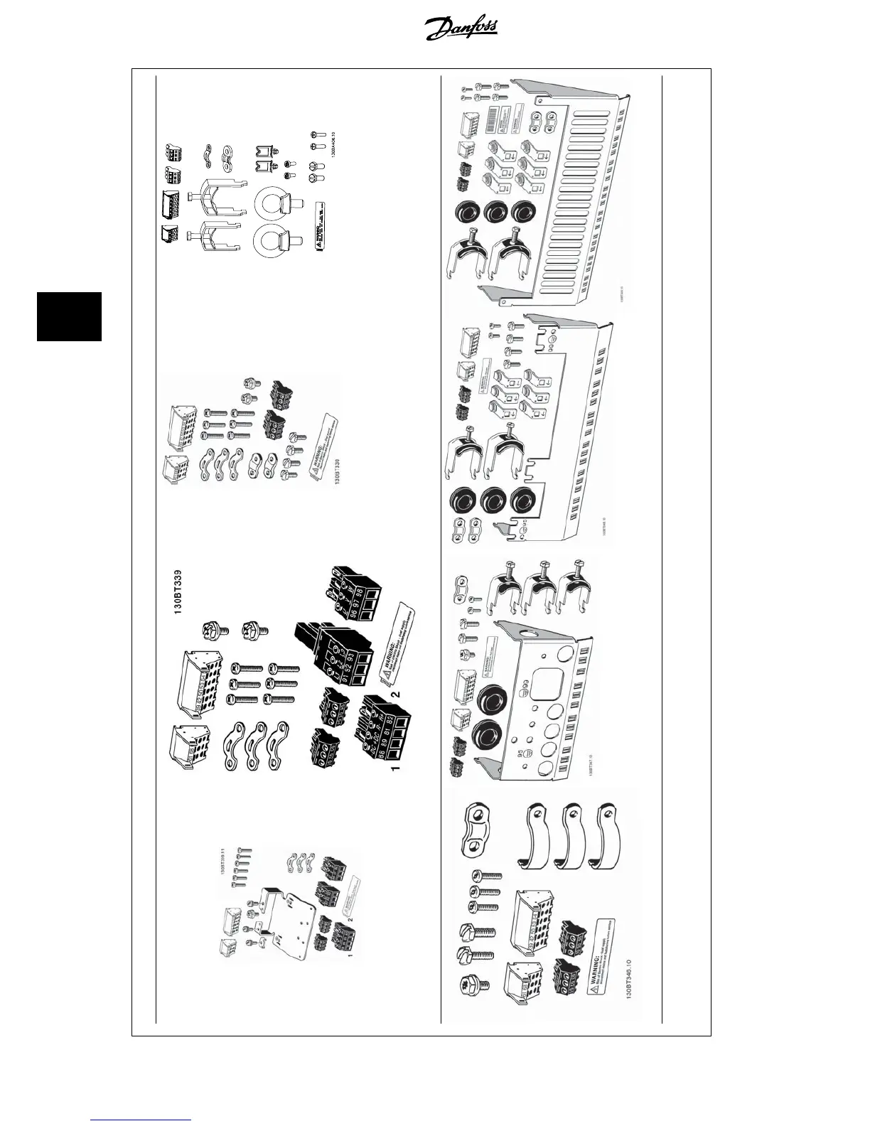
Accessory Bags: Find the following parts included in the frequency converter accessory bags
Frame sizes A1, A2 and A3 Frame size A5 Frame sizes B1 and B2 Frame sizes C1 and C2
Frame size B3 Frame size B4 Frame size C3 Frame size C4
1 + 2 only available in units with brake chopper. For DC link connection (Load sharing) the connector 1 can be ordered separately (Code no. 130B1064)
An eight pole connector is included in accessory bag for FC 102 without Safe Stop.
5.1.3 Accessory bags
5 How to Install VLT
®
HVAC Drive Design Guide
84
MG.11.B9.02 - VLT
®
is a registered Danfoss trademark
5

Table of Contents

Other manuals for Danfoss VLT HVAC

Questions and Answers:

Question and Answer IconNeed help?

Do you have a question about the Danfoss VLT HVAC and is the answer not in the manual?

Danfoss VLT HVAC Specifications

General IconGeneral
Enclosure RatingIP20, IP21, IP54, IP55, IP66
Storage Temperature Range-25°C to +70°C
Output Voltage Range0-100% of supply voltage
Communication ProtocolsModbus RTU, BACnet, Ethernet/IP, Profibus DP
Ambient Temperature Range-10°C to +50°C (without derating)
Relative Humidity5% to 95% non-condensing
AltitudeUp to 1000 m without derating
Cooling MethodAir cooled
ApplicationHVAC systems, Pumps, Fans, Compressors
Voltage Range200-240 V, 380-500 V, 525-600 V
Frequency Range0 Hz to 590 Hz

Related product manuals