The fan runs for the following reasons:
•
AMA.
•
DC Hold.
•
Pre-Mag.
•
DC Brake.
•
60% of nominal current is exceeded.
•
Specic heat sink temperature exceeded (power
size dependent).
The fan runs for minimum 10 minutes.
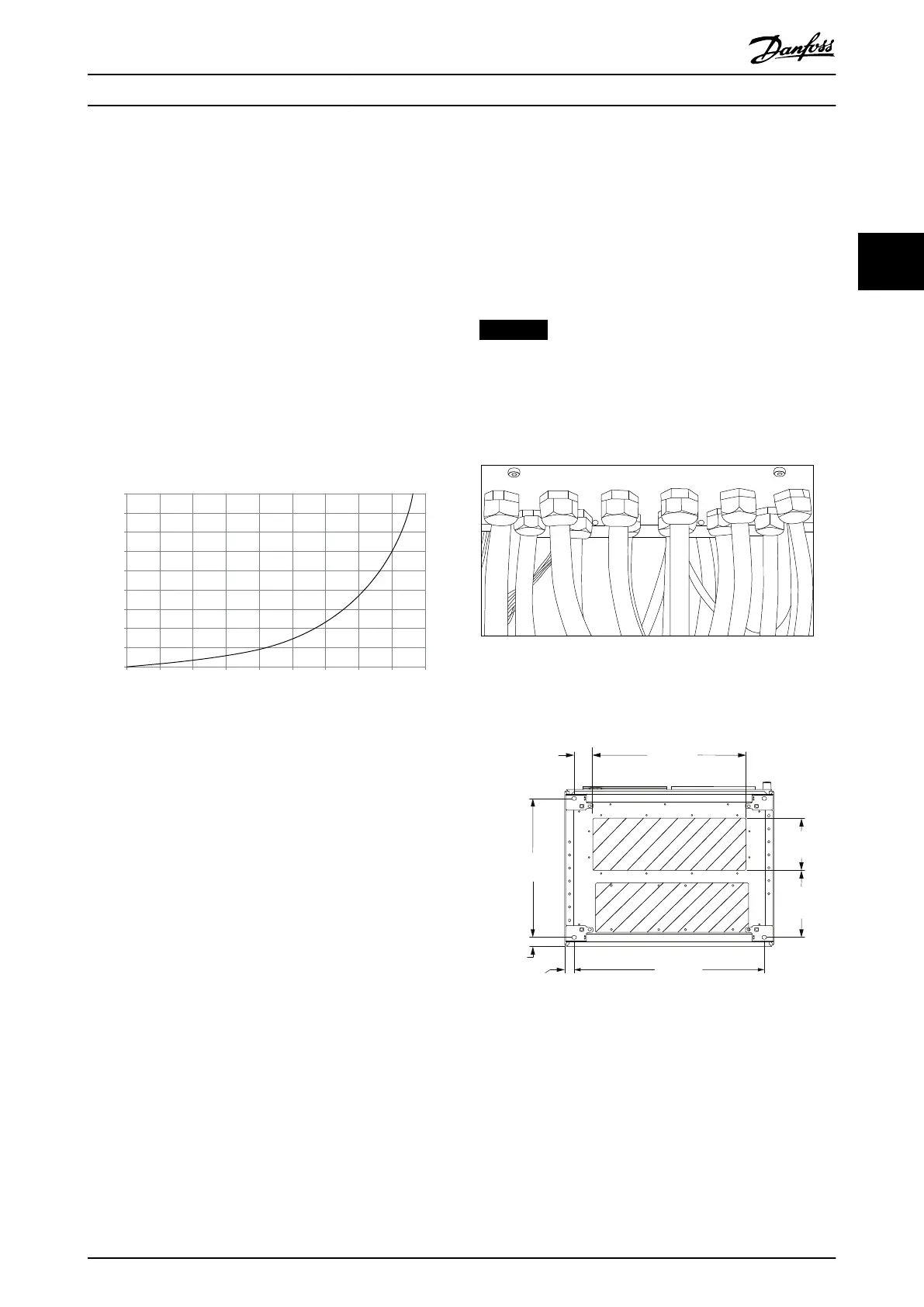
External ducts
If more duct work is added externally to the Rittal cabinet,
calculate the pressure drop in the ducting. To derate the
frequency converter according to the pressure drop, refer
to Illustration 3.22.
90
80
70
60
50
40
30
20
10
0
(%)
Drive Derating
0 25 50 75 100 125 150 175 225
130BB190.10
200
Pressure Change
Illustration 3.22 Enclosure Size F, Derating vs. Pressure Change
(Pa)
Drive air
ow: 985 m
3
/h (580 cfm)
3.2.6 Gland/Conduit Entry – IP21 (NEMA 1)
and IP54 (NEMA12)
Cables are connected through the gland plate from the
bottom. Remove the plate and plan where to place the
entry for the glands or conduits. Prepare holes in the
shaded areas on the drawings in Illustration 3.24 to
Illustration 3.31.
NOTICE
To ensure the specied protection degree, and proper
cooling of the unit, t the gland plate to the frequency
converter. If the gland plate is not mounted, the
frequency converter may trip on alarm 69, Pwr. Card
Temp
Illustration 3.23 Example of Proper Installation of the Gland
Plate
733.0
(28.86)
258.5
(10.18)
99.5
(7.85)
593.0
(23.33)
70.0
(2.76)
535.0
(21.06)
35.5
(1.40)
36.5
(1.44)
130BB533.12
Illustration 3.24 F8, Cable Entry Viewed from the Bottom of
the Frequency Converter
How to Install Operating Instructions
MG34Q402 Danfoss A/S © 04/2016 All rights reserved. 29
3 3
 Loading...


