AP20 Installation and Operating Guide Version 1.25
Appendix F. H338 Optical Film Card Option F-8 Document #: 9301H39200 Ver. 1.25
F4. Alignment
A-Chain alignment consists of calibrating the projector(s) optical film path, the solar cell, and the optical
preamp. These adjustments consist of both mechanical alignments on the projector(s) and software
settings in the AP20. Adjustments on the projector(s) optical heads differ depending on the manufacturer;
however the end results are the same. This section describes briefly the projectors optical head
adjustment, for detail adjustments refer to that projector manufacturer’s recommended procedure.
F4.1. Materials and equipment required
For initial mechanical alignment of the projectors optical head, the following is recommended or
required. These items are not supplied by Datasat Digital Entertainment.
• RTA – Real Time Analyzer with Microphone
• Oscilloscope
• Voltage meter
• Cotton swabs
• PC (lap top) and wireless router to connect into the AP20 using VNC (optional)
• Miscellaneous tools needed to make adjustments on projector optics mechanical alignment.
Test Films (not supplied by Datasat Digital Entertainment):
• 50% tone (Cat 69T)
• Pink noise (Cat 69P)
• Buzz Track (P35-BT)
• L/R (Cat 97)
• Illumination uniformity (Cat 566) optional
F4.2. Inspection and voltage check
Visually inspect the optical film path of the projector. Make sure all components are clean and in
good working order. The items that need to be checked are rollers, lateral guides, bearings,
dampener, etc. Use a cotton swab, lightly coated with lens cleaner, to wipe the optical lens. Check
the LED voltage and adjust it if necessary, as per the manufacturer’s recommended procedure.
F4.3. Wiring and Connections
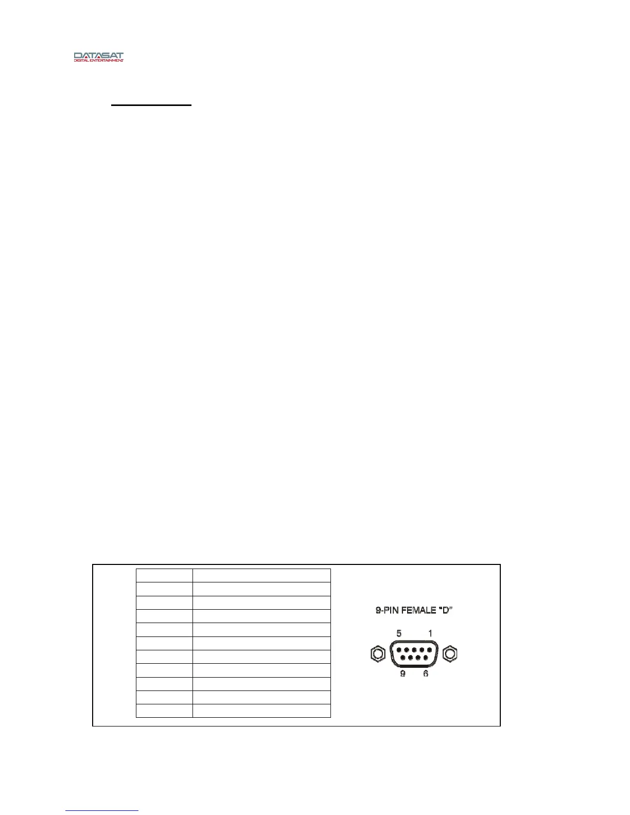
Projector 1 & 2 inputs on the AP20 are 9-pin female D-connectors. See Figure 8 below for pin
assignments. Input from the solar cell is a 9-pin Male D-connector.
Figure 8 – Solar Cell input pin assignment
PIN NO. DESCRIPTION
1 LEFT +
2 LEFT -
3 N.C.
4 RIGHT +
5 RIGHT -
6 LEFT ANALOG GND.
7 N.C.
8 N.C.
9 RIGHT ANALOG GND.