6/ Repair Procedures
6-10 1503-0151-000 5/26/0
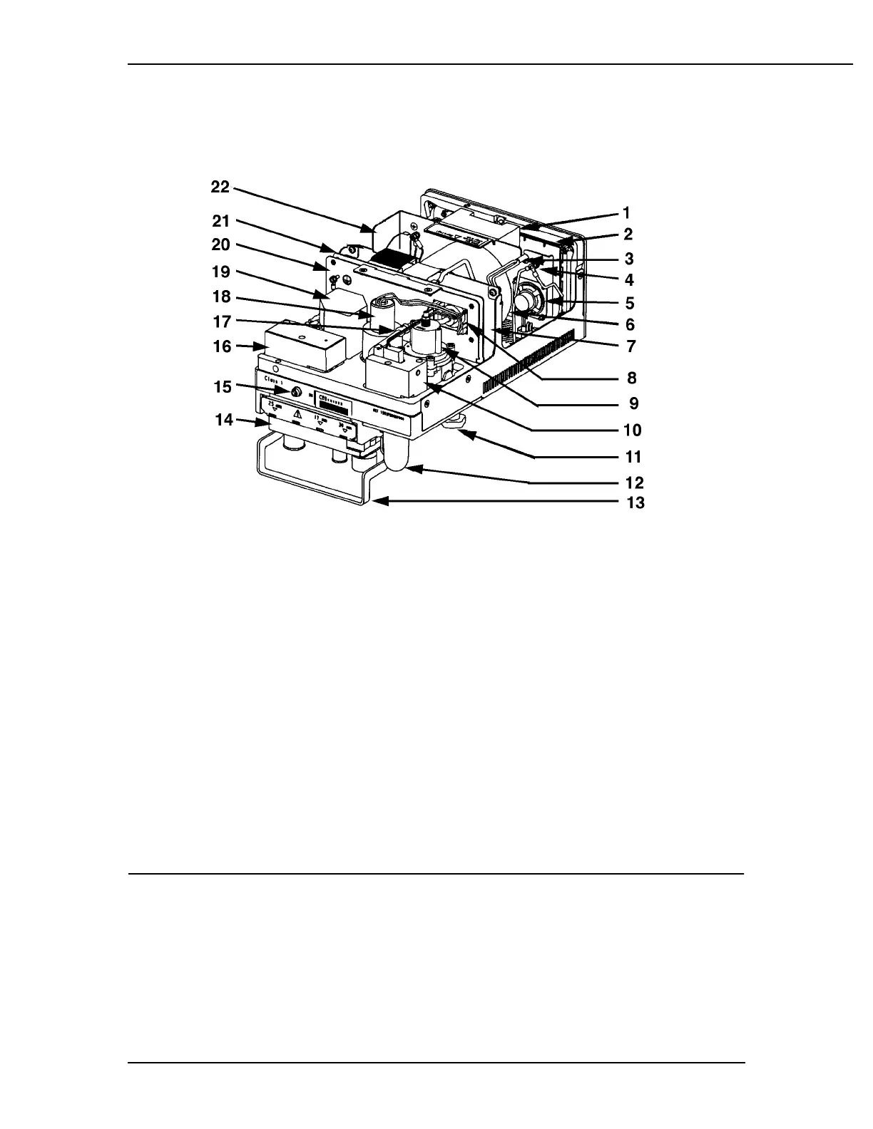
Figure 6-9
Sub assembly locations reference
1. Battery retainer
12. Supply gas filter
2. Front panel board 13. Locking handle
3. Battery harness 14. Exhalation valve block (manifold)
4. Ground wires 15. Pneumatic bleed resistor
5. Speaker 16. Mechanical over pressure valve
(MOBO)
6. Isolation transformer 17. Pneumatic quick connect
7. Power supply board 18. Flow control valve
8. Pressure transducer 19. Drive gas check valve
9. Regulator 20. Pneumatic/electronic barrier
10. Gas inlet valve (GIV) 21. Microcontroller board
11. Lock knob for mounting 22. Power module chassis