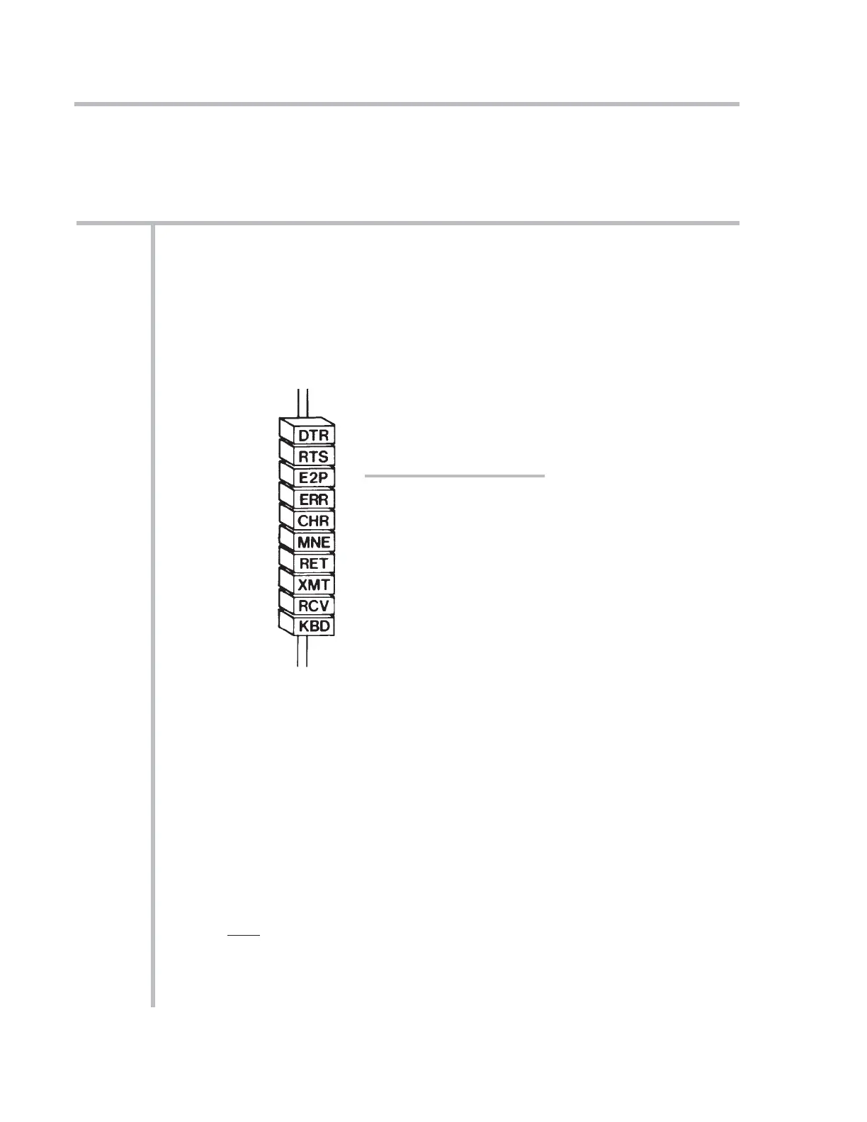
Your mainframe’s front-panel SYSTEM STATUS INDICATORS let you continuously
monitor the validity of various system communication links.* The top four lights
(or the first four from the left) are RED, to indicate “ERROR” or “ALERT” conditions.
The remaining lights are GREEN.
For “10KU” and “10K4T” mainframe versions, the status indicators are located
under the A-CARD SLOTS; for all other mainframes, they are located on the front
edge of the RS-232-C Interface Card, as shown in Fig. 1.4.**
DTR When this light is ON, it means that System 10 is not asserting DATA TER-
MINAL READY
. The system input buffer is full, and it is therefore not
ready to receive data
from the connected device. This light should be on
only during rapid, continuous computer outputs to System 10.
RTS When this light is ON, it means that System 10 has issued a REQUEST TO
SEND
to the connected device, but has not yet received an answering
CLEAR TO SEND.
This could indicate that the computer is currently too
busy to accept more data, or that some other factor is preventing trans-
mission (for instance, a disconnected cable). This light may blink during
normal operation, but in any event should be ON only during continuous
outputting by System 10.
1-21
SYSTEM STATUS INDICATORS
1.D
1.D SYSTEM STATUS INDICATORS
* These links relate to the EEPROM memory, an external KEYBOARD (if present), and the sys-
tem’s MAIN COMPUTER INTERFACE PORT. All “AUXILIARY” (10BACI-supplied) and “SATEL-
LITE” (10BD4- or 10BD1-supplied) interfaces have their own respective status indicators, for an
explanation of which see the respective subsection of Section 3 of this Guidebook.
** For a “10K1/10K2” mainframe, this is the combined Central Processor/Interface Card.
Fig. 1.4
System Status Indicators
SYSTEM 10 GUIDEBOOK
1.D SYSTEM STATUS INDICATORS