SETUP AND/OR OPERATING CONSIDERATIONS 10A78.5
AC STRAIN GAGE CARD 10A78
3 SETUP AND/OR OPERATING CONSIDERATIONS
3.a PHASE AND SYMMETRY ADJUSTMENT FOR ALL TRANS-
DUCERS EXCEPT A LEBOW 1800 SERIES TRANSDUCER
Before you do a “two-point” or “shunt” calibration of your 10A78 for the first time, you
should perform an initial “on-line”
phase and symmetry adjustment. When using a
Lebow 1800 Series Transducer (only), you should follow the special procedure
given in the next section. For
any other transducer, use the following procedure.
ONCE SET FOR YOUR TRANSDUCER, THIS ADJUSTMENT NEED NOT BE REPEATED
UNLESS A SIGNIFICANT CHANGE IN CABLE LENGTH OR CAPACITANCE IS
REQUIRED.
a. Turn ON the system EEPROM Switch and enter a
SCALING FACTOR (EMM)
command of
EMM x = m [CR]
where “x” is the Channel Number of the 10A78’s measurement channel, and “m”
is the
full-scale input range in the desired engineering units and with the desired
resolution.
b. Provide a “live” display of the data reported by Channel No. x.
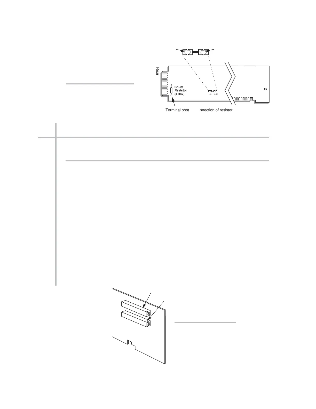
c. Without removing the 10A78 from its slot, locate the PHASE AND SYMMETRY
CONTROLS, which are accessible from the front of the card (see Fig. 3).