• setup of BIT-STATE, MESSAGE, and VIDEO PLAYBACK FIELDS
• specification of VISUAL EFFECTS for data, bit-state, message, and video play-
back fields
As mentioned earlier, some of these topics will be covered when we come to
LIMIT SETUP in Section 13. Setting the REFRESH RATE is covered in Section 10.
Optional VIDEO BARGRAPHS (requiring the
Model 10VGM500) will be treated in
Section 17, and optional VIDEO PLAYBACK FIELDS (requiring the
Model
10BDR64
), in Section 18.
6
SETUP OF ANALOG INPUTS:
TRANSDUCER CABLING
If you ordered sensor cables with your System 10, these will be equipped with
individual female 20- or 40-pin CONDITIONER CONNECTORS, all properly
labelled and “keyed.”
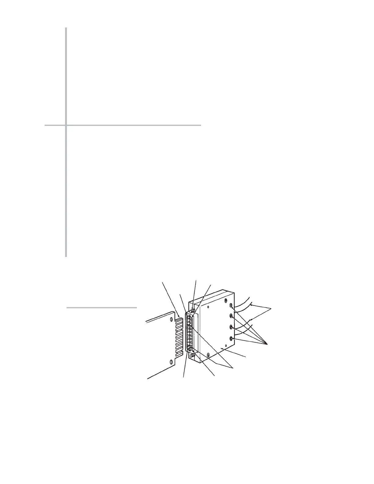
Fig. 6.1.a, below, shows the “standard” 20-pin connector for a Daytronic
“10A”
Conditioner Card, with internal solder terminals for up to eight separate transduc-
er cables. “10A” Thermocouple Conditioners like the Models 10A9-8C and
10A10-4 require special screw-terminal connectors, similar to that shown in Sec-
tion 1.E of the
System 10 Guidebook.*
Fig. 6.a.b shows a typical 40-pin connector for a Daytronic
“AA” Conditioner Card,
with labelled
screw terminals for direct connection of transducer cable leads.
If you’re supplying your own sensor cables, you should carefully read Section 1.E
of the
System 10 Guidebook, along with the individual conditioner card subsec-
tion(s) of Section 1.E.2
that apply to your system. All necessary cabling instruc-
tions are given here.
B - 15
“O
NTHE
A
IR
” (B-S
IZED
)
"10A"-Card
I/O Connector
(rear of mainframe)
"10A"
Conditioner
Card
20-Pin Conditioner
Connector
(No. 60322)
Pin 1
Pin A
Pin 10
Pin L
Cables to
Transducers
Cable Clamp-Bar
Screws
Captive Screw
(for mounting to
mainframe)
Connector
"Keys"
(to match slots in
card I/O Connector)
Fig. 6.1.a Standard “10A”
Conditioner Connector
*Several other “10A” cards require special I/O provisions. For example, the Model 10A68-2
Dual AC RMS Conditioner Card mates with a special connector board that has a separate
screw-terminal block for each input channel, and the Model 10A74-4C Quad Strain Gage
Track-Hold Conditioner Card will normally use a special Bridge Completion Connector in place
of the standard connector. See the specific subsection of
System 10 Guidebook Section 1.E.2
for complete details.
SETUP OF ANALOG INPUTS: TRANSDUCER CABLING
 Loading...